
Control approaches for making versatile and cost-effective step motors operate more smoothly, efficiently, and rapidly.
In this article we take a broad look at controlling step motors. We will run through some basic operating theory and then introduce a range of new techniques that have come online in the last ten-fifteen years. So, let’s get started!
Motors 101
Step motors are predominantly used for positioning applications, but they aren't the only game in town for that task. So let's start by pulling the camera way back and checking your overall choices.
Below is basic information on common motor choices for positioning motor applications. Note that there are a few other possible choices, such as AC Induction motors or piezo motors, but these three listed motor types represent the huge majority of applications in use today for general purpose motion control.
- Step motors - These motors are self-positioning, and therefore simple to use. They do not require an encoder to maintain their position nor do they require a servo control loop. Their main drawbacks are vibration and noise, and limited speed range. Like Brushless DC motors they must be "commutated" externally using a multi-phase drive.
- DC Brush motors - These motors require a position encoder for feedback and are stabilized using a PID (Proportional, Integral and Derivative) controller or other position loop controller. These motors do not require external phasing - give them some current and off they go. However, the mechanical brushes inside the motor which accomplish commutation may eventually wear out and fail.
- Brushless DC motors - These motors require servo control with an encoder for feedback as well as external electronic commutation. They have no brushes, however, and they provide high torque over a large speed range. Compared to DC Brush motors, Brushless DC motors today offer the 'go to' choice in servo control applications because their historically higher costs have come way down.
Stepping Right Along…
Congratulations, if you are reading this, it's because you want to learn more about step motors. So let's dive in with basic information on step motors and control techniques, followed by new techniques that reduce or even eliminate some of their traditional limitations.
Figure 1 shows typical waveforms for driving a step motor. Step motors are a multi-phase device, meaning two or more motor coils must be electronically driven to create motion. The amplifier must convert unphased command information such as pulse and direction signals into a set of correctly sequenced voltage commands to each coil of the motor. Most step motors have two coils (also called phases) although more exotic configurations such as 3-phase or 5-phase also exist.
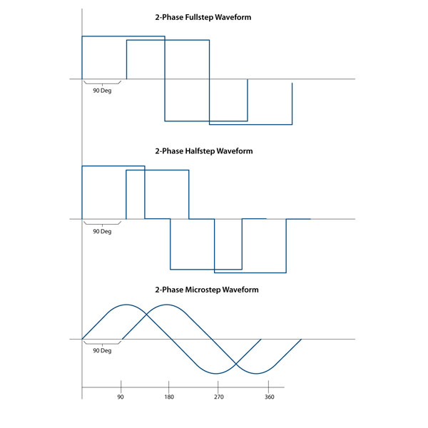
Figure 1: Step Motor Control Waveforms
In the world of step motors, the phasing techniques that the amplifiers employ are given special names such as full step, half step, or microstep control. These different techniques refer to the number of power levels that are applied to each motor coil during an electrical cycle.
A full step drive uses an “all-positive” or “all-negative” technique, a half step drive can separate the current into three distinct levels (all positive, zero, all negative), and a microstep drive can generate a more or less sinusoidal signal. The more the waveform resembles a sinusoid, the smoother and more precise the degree of control.
Whichever drive method is used, the motor moves forward or backward by altering the electrical phasing. A 'full' step means one 90 electrical degree movement. Step motors usually come constructed with 1.8 mechanical degree per full electrical step (90 electrical degrees). So this means a 1.8 degree stepper has 200 full steps per mechanical motor rotation.
If a microstepping scheme is used, you can calculate your positioning resolution (not accuracy - more on that in a moment) by multiplying the microsteps per full steps by the degrees per full step rating. Thus, if you use a microstep drive with 64 microsteps per full step and you use a 1.8 degree step motor with 200 full steps per motor rotation, you have 64 * 200 = 12,800 different commandable positions per motor rotation. This figure is the 'resolution' with which you can control the motor position.
Note that with step motors, accuracy and resolution are not exactly the same. This is because a step motor's mechanical response to the amplifier's output signals is not perfectly linear, nor is the magnetic holding torque perfectly stiff. These differences are generally small, but may be important depending on your application. It's worth nothing that some of the techniques we will discuss later on will help reduce this discrepancy.
Hanging Ten
As we look at some of the more advanced step motor control techniques, it's useful to get a more intuitive sense of what's happening inside the motor.
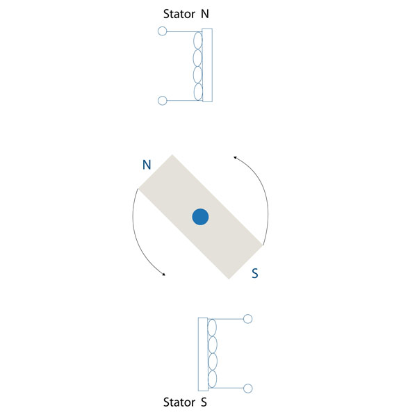
Figure 2: Bar Magnet Model
Like most motors, a spinning bar magnet that interacts with a magnetic field is a good place to start when thinking about what creates electromotive force in a step motor. In the case of the step motor, the rotor contains permanent magnets which interact with the stator's magnetic field (the stator is the outer portion of the motor that does not move) when the stator's coils are energized with current. This is shown in Figure 2.
When the stator coils are excited, a roughly sinusoidal force 'valley' is created which drives the step motor to to settle at a specific position. This is shown in Figure 3. The force valley is simply the torque on the rotor as it moves through a 360 degree electrical cycle. Wherever the curve is horizontal there is no torque, and wherever the curve is the steepest the torque is the largest.
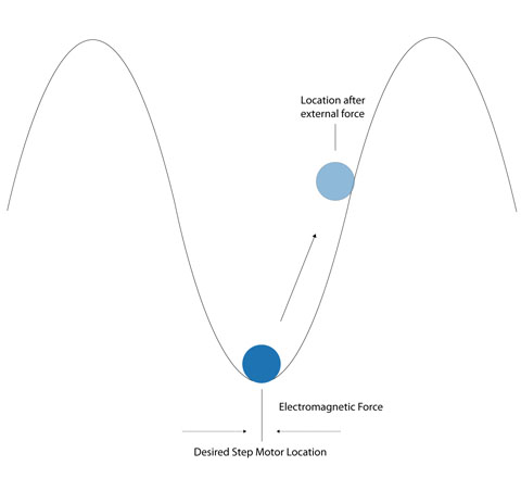
Figure 3: Force Valley Diagram
To create motion, the electronic controller moves this valley forward or backward (depending on the commanded direction of motion) by adjusting the coil phasing. The motor then 'falls' forward or backward in response. Think of a ball settling to the bottom of a trough or a surfer riding a wave.
I've Fallen And I Can't Keep Up
With this model in our minds, several aspects of step motor operation become clear. Thinking of the torque valley as a wave and adding the idea of a surfer explains the occasional tendency of the step motor to 'fall off the train' and coast rapidly to a stop during acceleration or at high speed.
What is happening is that the step motor and load cannot keep up with the request for motion and they lose step-lock, also known as synchrony, with the commanded profile. Just like a surfer who has been pushed over the top of the wave, once the condition starts, on-the-fly recovery (which is to say, getting back on the wave) is almost impossible - the profile proceeds even farther forward while the step motor comes to an unceremonious halt.
The valley metaphor helps explain another phenomenon, namely that under the influence of an outside force, the step motor does not always settle at the theoretical commanded position. This is because an outside force will tend to push the axis 'up the hill' to one side or the other, so the motor won't quite be at the theoretical location (the exact bottom of the valley) that you expected.
Yet another problem that stems from the open loop 'settling in the force valley' aspect of step motor operation is called mid-range instability. The symptom of this behavior is that there is a drop in available torque at a specific frequency located somewhere in the 'mid-range' of overall step rate output.
The instability is an interaction of the natural resonance frequency of the motor as it 'climbs' and 'falls back' around the valley target position (very much like a resonant spring), and the current control circuit. At the instability point, the effective current in each coil may lag excessively, reducing or even reversing damping effects in the system that normally counteract the tendency of the motor to resonate.
It's A Bird… It’s A Plane… It's An Advanced Control Technique
With this primer behind us, let’s delve into some advanced control techniques that improve motion smoothness and stability. At this point we will not add an encoder (we will later); because it turns out that a lot can be done just in the electronics.
Let's start with the fact that improving phasing smoothness will go a long way toward improving motion. So, the first thing you should try is to move past full step control, to half step or to microstepping control with at least 16 microsteps per full step.
As it turns out though, even when using a high end microstepping control technique, you will likely find that the motor does not move in perfectly equal increments. There is still some regular 'cogging' of the motion. This is because even when presented with perfectly sinusoidal coil currents, step motors do not respond with perfectly linear mechanical motion.
The reason for this is complicated, having to do with the rotor’s precise magnetic field shape as it interacts with the stator. But you have choices that will affect this phenomenon. Begin by making sure your motor is designed to be operated with a microstepping waveform. Next, consider using motors that can provide an improved response by utilizing a 'skewed rotor' design, or other technique to smooth the magnetic field interactions.
The Current State of Affairs
Once you have the right motor selected, pay attention to the current controller itself. Figure 4 shows a general diagram for the current controller used with a two-phase step motor controller.
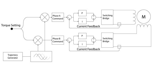
Figure 4: 2 Phase Current Controller
In a perfect world, the phase generator outputs a continuously varying desired current through each coil, and the current controller (sometimes called a current chopper) drives the coil so as to precisely match the actual current with the desired current command. In the real world this is seldom the case, and once again, not all current controllers are created equal.
A full four-quadrant controller is the gold standard, but may be a bit more expensive. A 'fixed off time' PWM (Pulse Width Modulation) controller provides two-quadrant control, and is generally fine for most applications, but it may struggle to accurately control the current at certain points, particularly at the zero crossing (when the current goes from negative to positive or vice versa).
Current control is a specialty of dedicated motion companies like PMD, so don't expect to become an expert on every aspect of this. What matters is that you match the amplifier to the application. Make sure you specify the speed range, the desired torque, and the voltage you plan to run the motor at. Your motion vendor should be able to recommend an amplifier that meets your performance and cost targets.
Shape Shifters Unite
For high accuracy applications (think camera tracking, XY tables, microscope stations, semiconductor equipment, etc..) you may want to consider a more advanced approach to the problem of non-linear motor response by 'shaping' the sinusoidal waveforms used to generate the microstep phasing through each coil.
The general idea is to attach a high accuracy encoder to the step motor (I have also successfully used a laser beam with a mirror located on the rotor, with the beam projecting onto a finely gradated ruler) and measure the motor response to a standard sinusoidal lookup table. Then the lookup table can be modified by slightly advancing or retarding the values, compensating for the non-linear response of the step motor.
As appealing as this technique is, it has limitations. You will find that there are significant motor to motor variations, as well as, possibly, amplifier to amplifier variations in the correspondence of amplifier command to motor movement. So unless you are prepared to characterize each and every motor in your system for each production unit that you ship, you will end up creating average compensation curves.
But still, this can make an important difference. Years ago I worked with a major security camera vendor to improve the cameras they sold for use in private poker rooms. Not surprisingly, the card players didn't like hearing the "buzz buzz" of the ‘eyes in the sky’ pointable cameras above their heads. By judiciously applying waveform shaping as well as using a more advanced current control technique, I was able to eliminate the audible noise and give this security camera vendor a big advantage in the marketplace.
That Not So Stable Feeling
Fancier current control techniques are the solution of choice for another major step motor problem, mid-range instability, discussed earlier. This is a problem that is endemic to the 'open loop' drive approach used with step motors and has therefore received a lot of research attention.
The simplest approach to reducing this problem is adjusting the trajectory profile to accelerate through the unstable frequency range. This helps by not giving time for a resonance to set in, effectively zooming past the problem frequency.
Other approaches in the 'easy' camp include adjusting the drive voltage, the winding configuration of the step motor, the overall step motor itself, and adding a mechanical damper.
If the problem persists, consider an amplifier which incorporates anti-resonance control. Different vendors give different names such as 'anti-resonance', 'electronic damping', or 'active damping' to describe these electronic techniques. A full discussion is beyond the scope of this article, but just be sure to work with a vendor that can help you select a method that will work well in your application.
You Lost Me
When operated without an encoder, the bane of step motors is lost steps. This is the tendency of the motor to not move the exact amount that you commanded. Usually, this is due to a loss of synchrony as described in the 'surfer' section of this article above. Alternatively, sometimes the motor encounters momentary drag that results in a small amount of lost position.
But either way, because step motors are inherently open loop, there is nothing that guarantees that this will not happen. Luckily, there are a few remedies. The simplest is to install a sensor somewhere in the range of motion of the mechanism that is driven by the step motor. Figure 5 shows this.
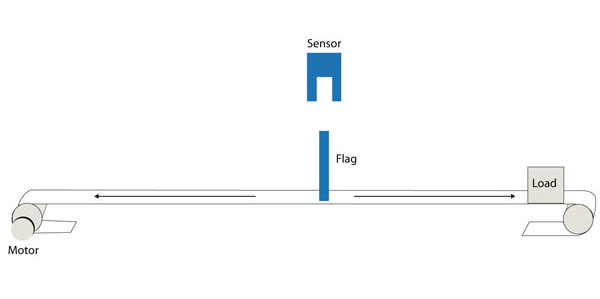
Figure 5: Position Capture Sensor
As the axis tracks along its range of motion, the sensor is tripped. The resultant pulse is then sent to the path planner, which uses it to capture its own instantaneous commanded position. If no steps have been lost, the captured position will be the same every time the axis sweeps past the sensor. If it is not, steps have been lost and the axis can be rehomed, or the machine shut down for service.
The upside to this approach is that it is simple. The downside is that it isn't very timely. The error is detected only when the sensor is traversed, regardless of where and when the steps were lost. For some applications this is no problem, but for many others this is not acceptable.
Automatic for the People
For those applications, we are getting closer to adding an encoder, which we will discuss in the next section. But there is one final approach that can be tried called 'automatic step loss detection'. This approach is implemented in the amplifier and relies on the fact that the voltage/current profile of the motor's coils looks different under normal operating conditions than it does under anomalous conditions such as when steps are lost.
Broadly speaking, this technique 'knows' what the anticipated motor current feedback waveforms look like, and detects when something unusual is observed. In providing this feature, some amplifiers will need to go through a training session so that the controller can learn what normal is for your system. Others, particularly those that are mated to a specific motor, come ready to operate.
Either way, the technique can be useful but it is not infallible. The main problem is false positives, where a hiccup in the axis motion such as from friction, an out-of-alignment bearing, or poorly mating gear teeth, can impart enough of a disturbance in the motor that the controller thinks something abnormal has happened - when in fact the motor is tracking correctly.
But for applications that can live with less than perfect step loss detection, this can be a useful feature that avoids the extra cost of an encoder.
You Encode Me
To deal with the various challenges of operating a step motor, many step motor applications routinely use an encoder. The encoder can be located either on the motor shaft or at the load, and is nearly always of the low-cost quadrature variety.
There are a number of ways you can use encoders in combination with trajectory moves. The simplest is to make the move and then compare the final position provided by the encoder with the anticipated location. If there is a discrepancy, you can make a second adjusting move, or flag the problem as requiring operator attention.
Because such motion hiccups are rare for properly designed motion systems, probably 90% of all applications that use an encoder with a step motor use this simple 'confirm everything is fine' control approach.
A more sophisticated version of this same approach is to specify an error window, measured in encoder counts, and continuously compare the commanded step position with the received encoder position. The instant the window is exceeded, the controller can be programmed to shut down the motion or notify the operator. This approach has the advantage that step loss detection is instantaneous.
There are a few, more elaborate, ways to use an encoder with a step motor, although it should be said that none of them have reached wide acceptance. Perhaps this is because step motors are revered for their simplicity, and if you have to get too fancy, you may be better off with a servo motor.
Some motion vendors provide a sort-of step/servo control approach, where an open loop control approach is used as in a standard step motor drive scheme, but a servo-like speed adjustment is implemented, just like a servo motor. There are no standards for this approach, and different vendors offer different methods, if in fact, they offer it at all.
Another approach is to operate the step motor as if it were a Brushless motor and commutate it actively based on the instantaneous position provided by the encoder. In this approach, the torque requested of the step motor is not fixed (as it is for a normal step motor driver) but rather is continuously adjusted by the controller.
For this to work, you need an encoder with fairly high resolution. Standard 1.8 degree step motors have 50 full commutation cycles, and to get reasonable accuracy you will want at least 40 positions per pole pair (a pole pair is four full steps or one complete electrical cycle). This puts the encoder for this application at 2,000 counts per mechanical rotation or higher.
This "step motor as a BLDC" technique has the advantage of running your motor more efficiently. Servo motors only output the torque needed to achieve a desired motion profile, while step motors are driven at the constant current that guarantees performance under worst case conditions. Since 'worst case' conditions are, by definition, unusual, this means that they use more current then they need most of the time.
Note that when used in this BLDC mode, the controller maintains the step motor's phase angle at a different location then a standard step motor controller. In this mode, the point of maximum torque, rather than the 'bottom' of the force valley, is the operational phase angle for the motor. This location is 90 degrees from the usual operating point of the step motor. Figure 6 shows this.
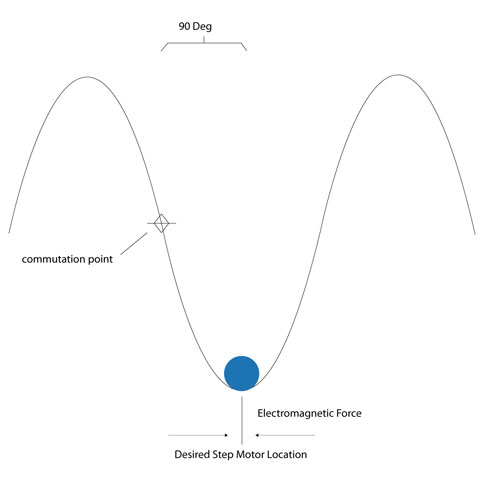
Figure 6: Normal vs. Commutation Phasing Point
Operating a step motor as a Brushless DC motor is by no means common, perhaps because it requires an encoder of rather high resolution. But if you want to try it, many products, including Performance Motion Devices' which support the capability. What you will find is that the motor operates in a very un-step motor like way. The sound profile is softer, and the motion is smoother.
Summary
I hope you have enjoyed this tutorial on step motor control techniques. Advanced electronics have significantly pushed the envelope on what you can do with a step motor, and many of the techniques add little or even no cost to the controller.
Ultimately, even after applying some of these techniques, you may find that step motors are not the way to go for your application. If this is the case, there are a lot of fine servo-based motion control ICs, modules, or boards available on the market that will serve your application's needs.
PMD Products That Provide Step Motor Control
PMD has been producing ICs that provide advanced position and torque control of step motor, DC Brush, and Brushless DC motors for more than twenty-five years. Since that time, we have also embedded these ICs into plug and play modules and boards. While different in packaging, all of these products are controlled by C-Motion, PMD's easy to use motion control language and are ideal for use in pick & place machines, laboratory equipment, liquid handling, and a wide variety of other high performance motion control applications.

Juno Step Motor Control ICs
The MC74113 and MC74113N are members of the Juno family of ICs and are perfect for building your own low cost, high performance microstepping or stepper servo motor controller. Juno ICs feature FOC (Field Oriented Control), two-phase waveform generation, high/low switching amplifier control signals, leg current sensing, and more. Available in packages as small as 7mm x 7mm and costing $12 in quantity, these ICs are an ideal solution to upgrade your existing pulse & direction controller, or for starting your next machine design project from scratch.
Learn more >>
MC58113 Series ICs
The MC58113 series of ICs are core members of PMD's popular Magellan Motion Control IC Family and provide advanced position control for BLDC, DC Brush, and step motors alike. Standard features include S-curve profiling, FOC (Field Oriented Control), high/low switch signal control, direct encoder & pulse & direction input, and much more. Whether used for laboratory automation, pump control, pointing systems, or general-purpose automation, the MC58113 family of chips are the ideal solution for your next machine design.
Learn more >>
ION Digital Drives
ION® Digital Drives combine a single axis Magellan IC and an ultra-efficient digital amplifier into a compact rugged package for control of step motors, DC Brush, and Brushless DC motors. In addition to advanced S-curve & trapezoidal point to point moves, cam profile support, and advanced motor performance analysis software, IONs are loaded with safety functions such as over current, over voltage, and over temperature detect. IONs are easy to use plug and play devices that will get your next pump controller, laboratory equipment, patient treatment, or automation design project up and running in a snap.
Learn more >>
Other PMD resources you might like:
- Step Motor Noise and How To Fix It
- New Control Technique Combines Servo Performance With Step Motor Cost
- Pushing the Limits of Motion Control
- Principles of Motor Selection
- Build vs Buy Of A Three Axis Motion Controller