
What's the best motor for your next machine design project?
When most engineers think about selecting a motor for their latest design, the highest level of excitement that can be expected is a heartfelt yawn. Motion control, which is tied to manufacturing automation, just isn't perceived as a fast-paced field. In the last several years, however, a battle for motor selection supremacy has been brewing - raising more than a few eyebrows, and ruffling more than a few feathers. The hubbub over motor selection has come within the context of dramatic changes in the motion control industry as a whole. Branching away from its historically machine-tool dominated past, motion control companies now use the latest electronic and software techniques to squeeze out the maximum possible performance from a given mechanical system.
Industries such as medical lab automation, medical device manufacturing, semiconductor capital equipment, precision pointing systems, an automation systems are just a few examples of the diversified industrial segments which utilize modern motion control techniques in their applications. In this article we will look at the issues concerning the selection of the right type of motor in positioning control applications. The focus will be on understanding how these motors are controlled, and how the choice of the control techniques affects the system cost.
Give me a motor, any motor
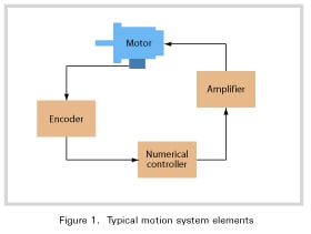 Motion control is the art and science of precisely controlling the position, velocity, and/or torque of a mechanical system. To accomplish this, motion control solutions consist of a numerical controller (often based on a Digital Signal Processor I.C.), a digital amplifier, and a motor. Figure 1 shows these elements.
The recent interest in the choice of motor has as much to do with the control system as a whole, as it has to do with the performance of the motor on its own. This is because different motors require different types of electronic controllers, thus affecting the cost and performance of the entire system.
The three major motor controllers that are commonly used in positioning control systems are:
- Step
- DC brush
- Brushless DC (permanent magnet)
It's important to note that there are many other motor types in existence, including AC Induction, variable reluctance, and synchronous AC. However these motor types are not typically used for positioning applications. Since these motors are more typically used for velocity and/or torque control, we will leave a detailed discussion of them for another time.
Positioning motors 101
Many electrical engineers are adept at reading motor specifications for total torque, size and power, but less well known are some of the implications of how the different motor types create torque and how these characteristics affect performance in areas such as smoothness, Mean Time Between Failure (MTBF), and the cost of the controller.
To understand these issues better let us start with a discussion of motor operation for each of the three motor types. Each motor type has particular characteristics such as preferred operating speed, smoothness, cost, etc., which provide many variables for us to compare and contrast.
The step motor, a self-positioning wonder
Step motors are “special” in that they are self-positioning and therefore do not require an encoder to operate. This immediately gives step motors a cost advantage over servo motors which require an encoder to operate in a position mode. Furthermore, step motors are sometimes constructed in such a way that they do not require any magnetic material in their rotor (the part of the motor that rotates) or the stator (the part that is connected to the motor frame). Instead, the “torque creating” part of a step motor can be constructed entirely of iron or similar materials that focuses the magnetic flux lines, and of copper wire which creates the electromagnetic force. Step motors also contain ball bearings and other mechanical items, but these items are common to all motors and do not help us distinguish one motor type from another.
In addition to being inexpensive to construct, step motors are also “brushless,” meaning there is no physical contact with the electrical portion of the rotor. This means that none of the problems that can occur with mechanical commutators, such as degradation due to wear or electrical arcing, occur with step motors. Finally, step motors produce a relatively high torque for a given package size, and also have a high holding (resting) torque.
Despite these advantages step motors have a few drawbacks. The most significant is that step motors create noise which is often audible, and induce vibrations that can disturb the load or affect parts of the system which are vibration sensitive. Vibration can be reduced using microstepping techniques or even mechanical dampers but these solutions seldom eliminate the problem completely.
Another significant limitation of step motors is that they have relatively low high-end speed. While step motors have been driven to operate at 10,000 RPM and beyond in some applications, for most systems, 5,000 RPM or less is the most that can be expected. In addition to a low top speed, the torque that is available from a step motor drops significantly at higher velocities.
It is mainly due to these limitations that step motors are generally not available in power ranges above several hundred watts. The most common “NEMA” motor sizes for step motors are 17, 23, and 34. Larger sizes are sometimes available but they are not as common.
You may also be interested in: Step Motor Noise and How to Fix It
DC brush, the workhorse
DC Brush (or DC servo) motors are used in a wide variety of applications which require positioning as well as for speed or torque control. By itself, however, a DC brush motor has no sense of position. This means it must be connected to an encoder for use in positioning applications. The encoder provides the position information and the controller drives the motor using a PID algorithm or similar scheme.
DC Brush motors are available in a large variety of sizes up to a kilowatt and beyond. They can operate at speeds of 10,000 RPM and even higher. Finally, DC servo motors are smooth and relatively quiet.
DC Brush motors have two primary disadvantages. The first is the very fact that they require a mechanical device to commutate the motor. The brushes of this type of motor can wear out, or cause electrical arcing which generates electro magnetic interference (EMI).
Typical Waveforms
Another disadvantage is that the DC servo motor has a relatively low torque output for a given size. This is due to the fact that the DC brush motor has current driven through its coils which are located in the rotor. The rotor is not “anchored” to the motor frame from a thermodynamic standpoint and therefore the total amount of energy that can be extracted from the coil is limited. This in turn limits the available torque output of DC servo motors.
Brushless DC, the high-flying overachiever
Brushless DC motors have been gaining in popularity in the last several years. This is because they provide a “no compromise” solution to servo control for many applications. Brushless DC motors are relatively smooth and quiet, and yet do not require mechanical brushes for commutation. In addition, Brushless DC motors do not drive current through the rotor. Instead, current is driven through the stator, which is solidly connected to the motor case allowing heat to be rapidly dissipated. This in turn allows the Brushless DC motor to generate high torque for a given package size.
Finally, Brushless DC motors are available in a wide variety of power ranges up to and beyond 1 kilowatt and they can be made to operate at very high speeds. Some motors can go up to 30,000 RPM and beyond.
 Despite these important advantages the BDLC motor has two main disadvantages:
- Cost: They are expensive compared to DC servo or step motors. This is due to the fact that the manufacturing volume of BLDC motors is not as high as for the other two motor types, and also due to the cost of the rare-earth magnetic materials that are used in the rotor.
- Complexity: Brushless DC motors must be commutated externally. This increases the complexity of the controls and also requires the installation of Hall sensors, or equivalent phasing tracks in an optical encoder disk. This increases the cost and complexity of the motor.
Now that we have been introduced to the characteristics of positioning motors let us examine some important issues related to how these motors are controlled. By developing a better understanding of motor control techniques we will be able to make more informed decisions about the best motor type for a given application.
Taking a brief look at... motor phasing
Motor phasing refers to the number of phases that are externally supported by the motor and which must be driven by the control system. A motor phase can be thought of as a complete electromagnetic circuit which must be driven by the motor controller (or digital amplifier) to create torque. Some motors, like a DC servo, have only a single phase (at least externally) while other motors, like the step motor, have 2, 3, or 5 phases.
If the motor presents more than a single phase to the outside world, it is referred to as a multi-phase device. If this is the case the motor controller must concern itself with the sequential excitation of these phases to maintain motor rotation. The technique of controlling the sequence of the phase excitation is known as commutation and will be discussed in the next section.
Each phase of a multi-phase motor requires an amplification circuit and therefore the number of phases a motor has is a key contributor to the cost of the overall system. For example, a 2-phase step motor, as the name implies, requires two separate amplification circuits, while a 3-phase Brushless DC motor will require three separate amplification circuits. If a motor amplifier is purchased as a complete unit, then all of this circuitry is contained within the amplifier. Because of the overhead cost of the amplifier’s case, connections, etc., the relative difference in cost between, for example, a DC servo motor amplifier and a Brushless DC motor amplifier is minimized. However, if you are constructing your own amplifier using ICs such as MOSFETs, drivers, etc., the choice of motor type will directly affect the number of components required and therefore the board space and board cost.
The following table summarizes the most common configurations of motor types, number of phases, and number of motor lead wires:
|
Motor Type
|
No. of Phases
|
No. of Motor Leads
|
|
Step motor
|
2, 3 or 5 (2 is most common)
|
Varies from 2 to 8
|
|
DC Servo
|
2
|
2
|
|
Brushless DC
|
2 or 3 (3 is most common)
|
4 from 2-phase
3 for 3-phase |
Taking a brief look at... motor commutation
Motor commutation refers to the technique used to properly sequence the various motor phases described above. By definition, therefore, a single phase device such as a DC brush motor does not require external commutation. Interestingly this does not mean the motor is not commutated, it just means the motor does not require external commutation. A DC Servo motor is commutated, however the commutation is performed inside the motor using brushes or contacts to continuously sequence the motor phases and keep the motor rotating.
For multi-phase devices, such as step motors or Brushess DC motors, commutation must be performed externally by the control electronics. In the case of a Brushess DC motor, commutation is typically performed using devices known as Hall-sensors. These signals allow the controller to excite each of the 3 motor phase coils at the right time based on the shaft angle of the motor. Hall sensors are used by the controller to create three motor coil currents located 120 electrical degrees apart.
Another popular Brushless DC motor commutation scheme is sinusoidal commutation which typically uses the motor’s position encoder to generate continuously varying sinusoidal signals. Using this scheme these signals are also phased 120 electrical degrees apart. This technique results in smoother motion with no discontinuities in the resultant motor torque output.
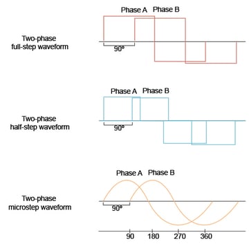
In the case of a step motor, most design engineers do not think of this device as requiring “commutation” but this is definitely what is occurring. In the world of step motors, the commutation techniques that the amplifiers employ are given special names such as full step, half step, or microstep drive. These different techniques refer to the number of different power levels that are applied to each motor coil during an electrical cycle.
A full step drive uses a full positive or full negative technique, a half step drive can separate the torque level into 3 distinct levels (full positive, 0 output, full negative) and a microstep drive can generate a more or less sinusoidal signal resulting in the maximum smoothness and highest degree of control. Whatever drive method is used, typical step motors have 2 phases and require that the phase signals be located 90 electrical degrees apart.
The following table summarizes the most common commutation techniques for each motor type along with the relative advantages and disadvantages of each method:
|
Motor Type
|
Commutation / Drive Method
|
Advantages & Disadvantages
|
|
Step motor
|
Full step
|
Simple to build but noisier and subject to instability at low speed.
|
|
Half step
|
Smoother and somewhat more stable at low speed.
|
|
|
Microstep
|
Smoothest motion but somewhat more complex to implement. This technique is gaining in popularity as the cost of electronics decreases.
|
|
|
DC Brush
|
None required
|
|
|
Brushless DC
|
Hall-based
|
Simple and inexpensive but may have greater torque ripple.
|
|
Sinusoidal
|
Smoother with less torque ripple but more complex to implement.
|
Taking a brief look at... motor position feedback
When used in positioning applications, position feedback is used to control the position of the motor (such as for a servo motor), or to confirm that the motor has arrived at the desired position (step motor). Servo motors such as DC brush or Brushless DC devices require position feedback to maintain their position at all times. These motors are positioned to a certain location or they are commanded to move through a certain path by continuously comparing the rotor position using the position feedback device (“the actual position”) with the desired instantaneous position “the target position”, and generating a motor command which is amplified by the motor drive circuit. This process is called servo control and typically uses a stabilization filter such as a PID (proportional, integral, derivative) to generate the motor command value.
Step motors operate on a completely different principle. As long as power is provided to the step motor coils the position will not change. By continuously “rotating” the phases through one electrical cycle after another, the motor is driven to move a precise number of steps or microsteps. Each quarter electrical cycle is referred to as a step and step motor controllers perform high speed step and direction generation to create continuous motion at a constant or accelerating velocity. The direction signal is used by the amplifier to determine the phase sequence. Changing the direction signal results in a reversal of motor direction.
Because the step motor does not require a feedback device to position itself most applications using this type of motor do not utilize a position encoder. Nevertheless there is an increasing trend toward use of position feedback devices even in step motor applications because of the additional safety provided.
There are many types of encoders available. The following table provides a summary:
|
Encoder Type
|
Advantages & Disadvantages
|
|
Incremental quadrature
|
Low cost, very common, and accurate but not absolute. Requires an initial home procedure.
|
|
Absolute optical
|
Provides absolute position up to 16 bits or even higher. Expensive.
|
|
Resolver
|
Provides absolute position and is very rugged but requires R&D (resolver to digital) converter circuit which can be expensive.
|
|
Precision potentiometer
|
Relatively inexpensive and absolute but requires A/D converter for use with digital controller. Also may drift over time.
|
|
Laser interferometer
|
Very accurate but expensive. Generally provides relative position information but some versions provide absolute information.
|
Summary
The truth about motor selection is that there isn’t, at least yet, a perfect motor for all applications. Motor choice may affected by a number of parameters including the mechanical characteristics of the control application, tolerance for noise, desired speed range, and cost.
To help you select the best motor for your application, the following chart summarizes what motors provide which advantages:
|
Desired Characteristic
|
Favors Use Of
|
Comments
|
|
Low cost
|
Step motor or DC brush
|
Brushless DC motor costs are doming down but are still well above step motor or DC brush motor costs.
|
|
Smooth operation (minimal noise or vibration)
|
DC brush or Brushless DC
|
Brushless DC motors can be smoother using high-performance commutation techniques such as sinusoidal commutation.
|
|
High speed operation
|
Brushless DC or DC servo
|
Step motors are not generally suitable for applications beyond 5,000 RPM.
|
|
High torque to size ratio
|
Brushless DC or step motor
|
Step motors provide high torque at relatively low speed only.
|
|
Ease of use
|
Step motor
|
No feedback required and no servo tuning.
|
|
Single phase operation (lower amplifier cost)
|
DC servo
|
Both step motor and BLDC motors are multi-phase devices that require more than one amplifier circuit per motor.
|
Before starting a motion control project try to determine your system’s requirements as a whole, factoring in the cost of the motor as well as the control system. Also, don't forget to factor in your own comfort level working with more complex technologies such as PID/servo control and external commutation.
Written by:
Chuck Lewin
Founder and CEO
Performance Motion Devices
Integrated circuit architecture allows for mixed motor types
In the modern world of automation, three motor types dominate the scene: step motors, DC brush motors, and Brushless DC motors.
At first glance, these motors seem to present drastically different control requirements to the designer or electrical engineer. Some motors require encoders, and other motors must be externally commutated. Some motors are multi-phase devices while others are single phase. Based on this, many designers tend to build their entire application with just one motor, thereby simplifying the motor controls. Unfortunately, different sections of a given machine may benefit from different motor types. Using just one motor type, therefore, inevitably leads to a compromise in the overall system performance.
Our family of motion control products change this. We make a family of IC-based motion controllers that perform "universal" motion control operations such as profile generation, encoder feedback, commutation, and motor signals generation.
To provide a unified interface to the user, our motion control chips (or ICs) provide a command language which is the same regardless of the motor type. For example, to create a smooth trapezoidal profile for a step, DC brush, or Brushless DC motor, the same command sequence is:
SET_POS xxxx
SET_VEL yyyy
SET_ACC zzzz
UPDATE
As the price of electronic motor controllers comes down, these high-performance motion ICs will address the growing interest in mixing and matching motor types within a machine design to optimize the performance and cost of the overall system.
Magellan & Juno Motion Control ICs
Magellan and Juno Motion Control ICs are perfect for building your own control board and achieving the smallest, lightest per axis controls. They feature the latest in servo motor control techniques including PID with feedforward, biquad filtering, current control with FOC, and PWM (Pulse Width Modulation) at up to 120 kHz. Magellan ICs are PMD's world-leading solution for positioning motion control, while the Juno products represent PMD's latest generation of high performance, low cost velocity & torque control ICs.
Learn more >>
Atlas Digital Amplifiers
Atlas Digital Amplifiers are compact single-axis amplifiers that provide high-performance torque control for Brushless DC, DC Brush, and Step motors. Atlas amplifiers come in both a vertical and horizontal mounting configuration and are available in three power ranges; 75W, 250W, and 500W. They are used for direct control of motor torque or in conjunction with higher-level motion controllers providing position or velocity control functions.
Learn more >>

Pro-Motion Analysis Software
Pro-Motion is PMD's easy-to-use Windows-based exerciser and motion analysis program. It offers ready-to-go capabilities your entire development team will be able to share. A step-by-step axis wizard allows designers to quickly and easily tune position loop, current loop, and field-oriented control motor parameters. Advanced users can access a complete motion analysis package with Bode plot generation and auto-tuning.
Learn more >>
You may also be interested in:
- Mobile and Portable Automation Demands Light, Efficient, and Cool Operation
- Precision Fluid Handling: It's All In The Pump
- Precision Fluid Handling: Taking Lab Automation To The Next Level
- Advanced Motion Control of Servo and Step Motors
- S-Curve Motion Profiles - Vital For Optimizing Machine Performance
- Improving Liquid Handling Pumping Through Optimized Feedback