
Many motion applications require precise synchronization of one or more motion axes. In this deep dive we will run through some of the important approaches toward motion synchronization and have some fun with a video from the PMD Corp. lab that shows motion synchronization in action.
On Your Mark, Get Set...
One simple form of motion control synchronization, and one still very widely used, is an external signal trigger that causes a synchronized change in the profile for one or more axes. This setup is shown in Figure 1.
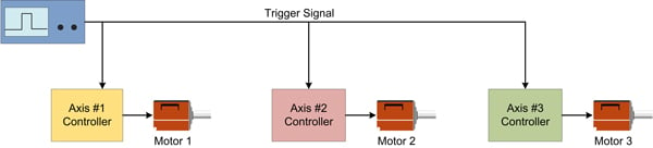
Figure 1: External signal trigger
Modern motion controllers allow a range of automatic trigger conditions (sometimes also called breakpoints) so that axes can be started, stopped or otherwise altered upon an external signal change, and so that the triggering condition can be nearly any combination of signal conditions.
In a typical application, the host controller pre-loads a new set of profile parameters and sets a breakpoint event to occur upon the desired external signal condition. When the signal reaches the desired state, the motion controller automatically initiates the new motion profile.
I Drift Therefore I Am
There are several applications where this approach won't work. One is if there is a need for synchronization between axes during motion, not just at the start of motion.
Why would two or more axes get out of synch during a motion? The reason is that motion controllers run their clocks from an internal oscillator. Since each oscillator provides a slightly different frequency, drift can slowly accumulate between multiple axes.
For most applications, because the moves are short, or because it is OK for axes to arrive at slightly different times, this is not a problem. But where it is, one solution is to explicitly synchronize the servo loop rates of each controller.
This can be done by arranging for one of the motion controllers to serve as the 'master' by generating a 'synch' or 'strobe' signal, which is then input by one or more slave controllers. Figure 2 shows such a setup.
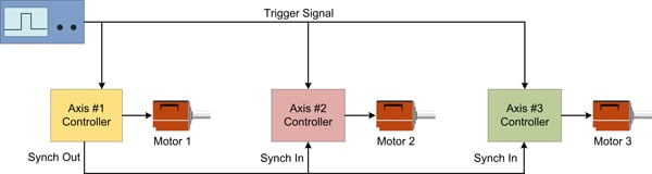
Figure 2: Using a motion controller to sync axes
It should be noted that the same benefit of explicit axis synchronization occurs automatically using a multi-axis controller rather than a chain of single-axis controllers. This is because multi-axis controllers use one master internal clock and therefore their servo loops are explicitly synchronized.
Get Your Gear On
What if synchronization is more than a matter of keeping axes coordinated with themselves? Consider the application of a robotic arm that must track the speed of an external conveyor. In this application, the conveyor speed may not be exactly known and therefore the robot arm must somehow be synchronized by a signal that changes constantly.
Enter electronic gearing, and its more sophisticated cousin electronic CAMming. Electronic gearing utilizes an external position data stream, nearly always quadrature encoder signals, to provide the master drumbeat by which all motions occur. Figure 3 shows such an application.
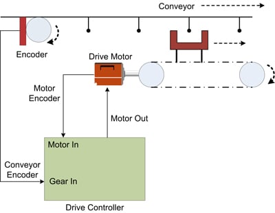
Figure 3: Electronic gearing utilizing an external position data stream
To make electronic gearing work, the host specifies the ratio of driven-motor output counts for each input encoder count. Multiple axes can be driven at different ratios, allowing, for example, a continuous web to be guided by rollers of different diameters.
Additional features of electronic gears include continuously changeable gear ratios, resulting in smoother starts and stops, and the ability to track an internal axis position, rather than an external encoder data stream. This allows, for example, multi-axis straight-line moves to be drawn, even while the profile moves through a complex velocity profile such as an s-curve.
CAM We Talk?
A more sophisticated version of an electronic gear is an electronic CAM, shown in Figure 4. An electronic CAM also takes an input position data stream, such as from an external encoder, but uses this input position as an index to a lookup table, the contents of which, in turn, determine the output command position of the driven motor.
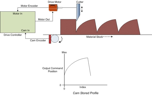
Figure 4: An electronic CAM uses an external encoder to determine the output command position
If multiple axes are controlled by cams, it is easy to create multi-dimensional shapes. For example, to draw circles or ovals from a linear input motion, sinusoids would be loaded into the lookup table, comprising the X and Y components of the circular shape. More commonly, cams are used to implement kinematically complex relationships between axes, such as occur with a SCARA-style robot (Selective Compliance Assembly Robot Arm).
Just as with electronic gearing, cams can track an internal axis as well as an external encoder data stream. When tracking an internal signal, one axis acts as the master and the other axes act as followers using the specified cam profiles.
CAM lookup table schemes come in various flavors to control how the output position is generated. There are lots of vendor-specific variations, but the basic idea is that cams can generate cyclical paths that always return to the same location, or paths that generate a net positive or negative position path.
I've Got The World On A Lookup Table
To work in the real world, it is important that the cam profile be at the correct 'phase' as it moves through its motion. Or expressed another way, it is important that the cam profile be at the correct output lookup index for a given input position. If this is not the case, to borrow the circle example from before, the drawn object might not be a circle but a tilted ellipse.
Motion controllers with CAM profiles offer a few ways to manage this by allowing an offset to be inserted into the index lookup. While moving, introducing or changing this offset should be done smoothly so that the change in offset does not cause an abrupt change in cam output.
Finally, for obvious reasons, changing the cam shape (the loaded CAM profile) while it is being used is not recommended. For systems that must constantly be on the go, however, a common switchover scheme is to use a 'foreground' CAM profile for active motion and a 'background' profile for loading new profiles. By carefully synchronizing the changeover of the foreground with the background, it is possible to switch on-the-fly with no abrupt changes in motion.
The Network Is The Motion Computer
As is often the case, no motion controller discussion is complete without a mention of distributed digital control networks. In fact, a primary use of digital control networks for motion control such as CANopen, EtherCAT and SERCOS is to provide tight multi-axis synchronization amongst a network of single axis modules.
Some digital networks, particularly those that utilize the synchronizing protocol IEEE 1588 PTP (Precision Time Protocol), can synchronize axes to very high accuracies, just as if a physical 'strobe' signal were connecting each module.
Building a motion controller using one of these synchronized protocols may or may not be your cup of tea, because while fast, the control languages provided by these systems need a lot of attention from the host.
The most common approach requires the host to send a continuous stream of PVT (position, velocity, time) points for each controlled axis, generally about once every 10mSec or faster.
For CNC applications, plotters and a few other applications, there are packaged PC-based software programs that do the heavy lifting. But for general purpose motion applications such as medical, scientific and most machine automation, this software would likely have to be written by the user.
To The Laboratory!
To wrap up our discussion of synchronized motion, we have prepared a demonstration, which is diagrammed in Figure 5.
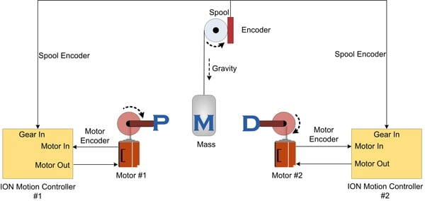
Figure 5: Position encoder data stream is provided by a falling weight connected by a thin wire
In this setup, a position encoder data stream is provided by a falling weight connected, by a thin wire, to a rotating spool/encoder. This encoder data stream is fed into two separate ION Digital Drives, which, in turn, drive two Brushless DC servo motors.
The position of each motor is commanded via the ION's electronic gear profile mode. Everything is arranged so that the falling weight and the two ION-driven motors arrive at the same point in time and space.
Even though the weight continually accelerates at 9.8 m/sec2, the IONs can easily track the changing speed of the falling 500g weight, as the high-speed camera shows!
Video: Wide Angle Shot of Synchronized Motion Move
PMD Motion That Provides Synchronized Precision
PMD has been producing motion control ICs that provide advanced motion control of servo and step motors for more than thirty years. Since that time, we have also embedded our ICs into plug-and-play modules and boards. While different in packaging, all PMD products are controlled by C-Motion, our easy-to-use motion control language and is ideal for use in medical, laboratory, semiconductor, robotic, and industrial motion control applications.
Magellan & Juno Motion Control ICs
Magellan and Juno Motion Control ICs are perfect for building your own control board and achieving the lowest cost per axis. They feature the latest in servo motor control techniques including PID with feedforward, biquad filtering, current control with FOC, and PWM (Pulse Width Modulation) at up to 120 kHz. Magellan ICs are PMD's world-leading solution for positioning motion control, while the Juno products represent PMD's latest generation of high performance, low cost velocity & torque control ICs.
Learn more >>
ION Digital Drives
ION Digital Drives have a Magellan IC at their core and combine this with a high power digital amplifier to create a compact rugged cable-connected module. Whether used for S-curve point to point moves, high speed spindle control, or your latest robotic design challenge, IONs are cost effective plug and play devices that will get your application up and running in a snap.
Learn more >>
Prodigy Motion Control Boards
Prodigy Motion Control Boards come in various form factors including PC-104, standalone, and standalone with built in Atlas Amplifiers (Prodigy/CME Machine Controller). In addition to ultra-smooth 7-phase S-curve profiling, these cards provide multi-dimensional synchronized contouring, electronic gearing, and a range of other features to form the core of your next machine design project.
Learn more >>
Related articles:
- Techniques That Improve Automated Packaging Equipment Performance
- Motion Kinematics
- Optimizing A Control Architecture for High Accuracy Syringe Dispensing
- Motion Controller Design Architectures - A Deep Dive
- Position Encoder Deep Dive: New Measurement Techniques Drive New Formats