
In this article we will focus on servo actuators that function as end effectors, often mounted on transport systems such as robotics arms and gantries. These devices include linear actuators, force feedback actuators, voice coils, and more. Understanding their capabilities and properties will help you ensure that your next application will deliver the goods without dropping the ball!
Introduction
Motors and end effectors come in many shapes and sizes but, compared to actuators that transport an object from point A to point B and focus on position control, end effectors commonly also integrate force sensing to ensure that objects being carried aren’t crushed or dropped.
Interestingly, the sensing function may not require a separate physical hardware device. It may instead be achieved by electronics that measure current flow through the actuator coils with a high precision thereby allowing a sensed torque to be inferred.
Finally, we will delve into the relationship between servo actuators, force feedback, haptics, and VR (virtual reality). This is an interesting subject where servo-based actuators can play a key role by simulating a physical experience.
So grab your squeeze ball, sit back, and relax as we get a grip on servo based end effectors and force control.
You had me at linear
Any discussion of end effectors starts with a discussion of linear servo actuators. There are a few varieties but ironically the most common configuration actually uses a rotary motor coupled with a lead screw to convert the motor’s rotation into linear motion. This is shown in Figure 1.
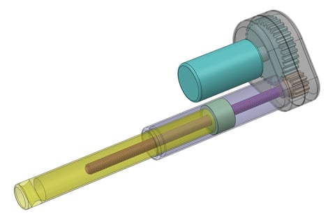
Figure 1: Linear Actuator Using Rotary Motor & Lead Screw
The rotary motor used is most often a DC Brush or Brushless DC type. But as it turns out a step motor can also be used. With a step motor there is no encoder because step motors are devices that can inherently control position.
Rotary motor to linear actuators such as this come in a vast variety of sizes, strokes, and force outputs. Because of the way force is generated - by rotating a motor and then mechanically converting the rotational torque into linear force, these actuators have high force output per unit of weight. In fact they are even used as an alternative to hydraulic pistons in some applications. They have only moderate acceleration and speed, however, again for the same reason – the motor’s rotation is mechanically reduced by the gearing mechanism.
At low to medium torque output levels the most common application for actuators of this type is positioning. If a servo motor is used the rotary motor’s encoder provides feedback to the servo control system which allows complex trapezoidal or even s-curve profiles to be executed for end point position control. The delivered positional accuracy is a function of the encoder resolution and the gearing system.
Generally this type of actuator is used for modestly precise applications where ultra high positioning accuracy is not a requirement. But the overall range of applications that this type of actuator is used in is vast. They include electronics manufacturing machinery, semiconductor equipment, bio tech and laboratory automation, textile, industrial automation, and more.
An interesting variation of this actuator is the force feedback linear actuator. This type of actuator starts with the same motor and gear mechanism but adds an external force sensor, generally a strain gauge-based load cell and a corresponding control loop that allows precise force control. We will talk more about the control scheme used with such an actuator a bit later on.
May I be direct?
The second category of linear servo actuators is Direct Drive Linear Brushless DC motors. Like a normal rotary Brushless DC motor, these are commutated motors which typically use an encoder for position control. Brushless DC motors are commutated electronically and therefore compared to DC Brush motors have no wear and tear of the commutating brushes. Direct drive here means linear motion is directly generated by the motor coils and magnets. No gears or lead screws are needed.
The diagram below shows how this is achieved. The linear version of the Brushless DC motor is essentially an unwrapped rotary motor. They both have a stator – the part that houses the coils, and they both have a rotor – the part that contains the permanent magnets (although it should be mentioned that rotor is a confusing term for a linear motor since it doesn’t rotate. Nevertheless, we will use this term because there is no other standard accepted term for this part of the motor in a linear motor).
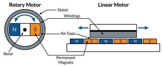
Figure 2: Direct Drive Linear Brushless DC Motor
Two different configurations of the stator and rotor are possible, one where the stator (the part with the coils) is stationary and the rotor (the part with the magnets) moves, and the opposite configuration where the stator moves and the rotor is stationary. Both of these configurations are shown below:
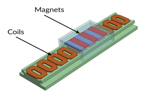
Figure 3a: Linear Brushless DC Motor with Stationary Stator
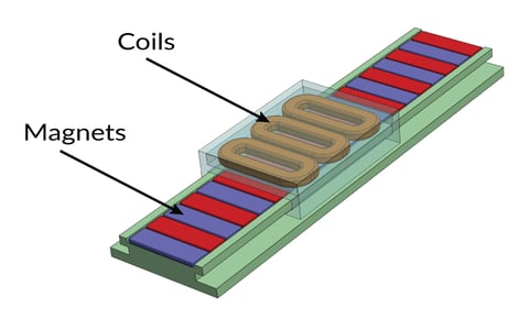
Figure 3b: Linear Brushless DC Motor with Moving Stator
There is a different mechanical arrangement of the motor which uses a rod-shaped rotor as opposed to the ‘track’ shaped configurations shown above. The rod contains the magnets and as before, either the rod can move with the stator staying stationary or the rod can be stationary with the stator travelling across it. Such actuators are shown in the diagram below.
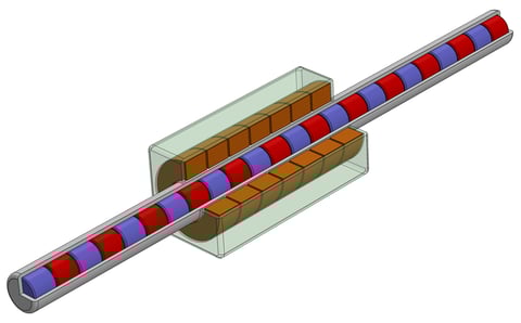
Figure 4: Linear Brushless DC Motor with Rod-Shaped Rotor
Whichever arrangement is used the linear Brushless DC motor is the workhorse for applications that demand ultra high reliability and fast response time. Compared to rotary to linear actuators discussed earlier direct drive motors have very high acceleration. Torque output is low to moderate but with the use of rare earth magnets can actually be surprisingly high.
Although direct drive motors are more expensive they still find frequent use in industries such as laboratory automation, semiconductor equipment, and electronics manufacturing equipment.
Before closing, an important quality of direct drive actuators is that force can be controlled rather precisely without the need of a force sensor. As long as high-quality bearings are used so that external drag is minimal, external torque presented to the actuator will be ‘felt’ directly by the servo system.
By comparison, with a rotary to linear converting actuator described earlier reflected forces are not felt by the servo as accurately. This is due to the internal gearing of such a device and the attendant friction. Friction ‘consumes’ the external force before it can be delivered to the motor and sensed by the servo controller, resulting in a reduced ability to accurately sense force via the servo controller.
We will talk more about force control in both of these actuator types a bit later.
Tap tap, is this on?
Another important category of direct drive linear actuators is the Linear DC Motor, which in turn has two sub-flavors: a moving magnetic rod arrangement, and a voice coil arrangement. The first of these is shown below.
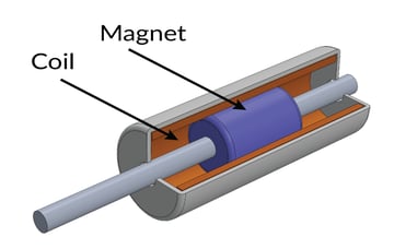
Figure 5: Moving Magnet Linear DC Motor Actuator
The magnetic rod style DC linear actuator can deliver modest torques and speeds with a small to modest stroke distance. Its main advantage is simplicity and therefore reliability and low cost. When the coils are energized the magnetic fields interact with magnets mounted on the rod which in turn generate force.
An actuator such as this can be purchased as a packaged unit already containing bearings supporting the rod, or as an open frame where the machine designer must supply the bearing support for the rod.
One might be forgiven for thinking that actuators of this type are solenoids, but solenoids are different because their moving component, called the armature, contains no magnets. Force generation in solenoids comes from the change in coil inductance that occurs as the armature, which is in fact made of some sort of ferrous metal, moves into or out of the energized coil.
Solenoids are common in factory floor applications where a simple ‘bang bang’ motion is required. For example a pin must be extended or retracted under electric control. But they are uncommon for use as the end effector carried by a gantry or robotic arm due to their relatively crude and uncontrolled motion output.
Voice coil actuators reverse the role of the stator and the rod magnets. This type of actuator generally has a short stroke, modest torque output, and extremely fast response time. The speed is due to the fact that the moving portion can be very light, consisting of little more than the motor coils themselves held together by an adhesive such as epoxy.
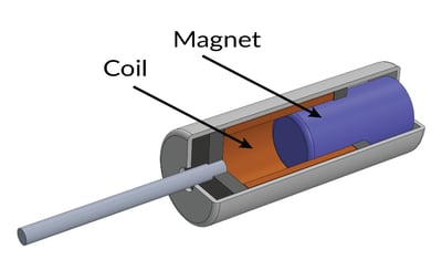
Figure 6: Voice Coil DC Motor Actuator
The drawing above shows a voice coil motor with a protruding rod, but many voice coils ‘actuate’ air or light rather than a mechanical rod. A stereo HIFI speaker is a classic example of such a voice coil, pushing a thin flat membrane which results in sound waves being created. Similarly, if the membrane is a mirror the reflection of light waves can be controlled at high frequency.
Note that both of these two DC linear actuator types can be coupled with a sensor to provide programmable positioning. In this configuration they are driven by a servo controller which continually adjusts the coil current to maintain a commanded position or torque.
Applications for positioning linear DC motor or voice coil motors are varied and include precision optics, scientific instruments, valve controllers, and others.
No, there is another
For a discussion of linear actuators, especially those used in high precision applications, one last actuator type must be mentioned namely the Piezo motor shown in Figure 7.
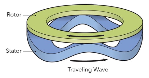
Figure 7: Piezo Motor
Piezo motors, which may be assembled in both a linear and rotary configuration, are electromechanical devices which use the elastic deformation of piezoelectric materials in conjunction with specialized electronics to control forward and backward motion.
To create motion the electronics set up a standing wave in the piezoelectric material (which functions as the motor stator) that directly contacts a textured platen functioning as the rotor. By controlling the phase of the standing wave forwards or backwards motion occurs. Piezo motors are seldom used for force control but excel in positioning applications, especially those that require small, precise strokes.
May the force control be with you
With this primer on linear actuators complete, let’s talk about one of the key differences between motors used for transport and motors used as end effectors. This difference is the need for force control. End effectors often care just as much (and sometimes more) about the force applied by the actuator as the position of the actuator.
Examples of applications where force control is critical include grippers, screw-cap applicators, web tensioners, press-fit tools, packaging equipment, and others.
A robotic gripper is a good model to understand how sensing and controlling force can be important for end effector applications. In a gripper, the object being carried may vary in size or orientation resulting in a different mechanical engagement point. But once contact is made the gripper should apply a consistent force on the object – large enough to hold it securely but not so large as to damage it.
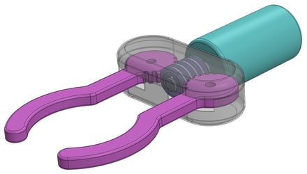
Figure 8: Example of Robotic Gripper Mechanism
How can this kind of force control be achieved? There are several techniques but two popular approaches could be called Stop Trajectory When Force Threshold Reached, and Continue Trajectory But Limit Force Output. Both are detailed below.
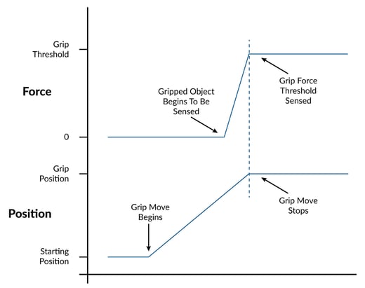
Figure 9: Stop Trajectory When Force Threshold Reached
In the first approach the gripper is controlled by a servo PID which continuously monitors the motor torque command which can be converted to applied torque by knowing the motors’ torque output to current (amperage) ratio. At the start, the gripper is not in contact with the object and begins a trajectory move to approach the object to be gripped. As the move proceeds, at some point the gripper begins to make contact and this is sensed in the servo loop as the motor command torque needed to follow the commanded trajectory increases. Once the desired grip force has been achieved the motion profile is halted. Note that the force ramp is an indicator of the compliance of the object being gripped. A more compliant object would result in a flatter force ramp.
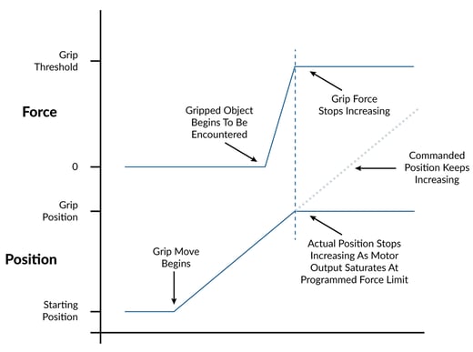
Figure 10: Continue Trajectory But Limit Force Output
In the second approach the gripper similarly approaches the object using a commanded trajectory move but the servo loop does not monitor the force output of the servo loop. Instead, a current output limit is installed in the servo loop so that even if the PID tries to follow the trajectory, the force it applies is no greater than the desired force threshold. At the point where the grip force equals the desired threshold the commanded trajectory continues moving but the actual position stops, resulting in the servo error rapidly increasing.
Oh servo! My servo!
What advanced algorithmic magic is needed to detect force in a servo control loop? As it turns out no magic at all. The common PID loop can implement both of the strategies described above as long as it has the ability to record and compare the output torque command (first approach described above) and as long as it supports a programmable torque limit (second approach).
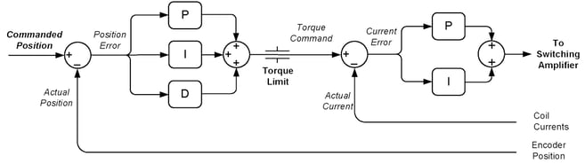
Figure 11: PID Position Loop with Torque Limit and Torque Loop
The diagram above shows what such a PID loop typically looks like. Note that there are two parts to this loop: a position loop and a current loop (also called a torque loop). The current loop is critical because accurate force control here is predicated on the ability to output a precise current through the motor coils. This in turn is enabled by the availability of accurate motor coil current sensors; generally either Hall effect sensors or dropping resistors located in the amplifier.
The other assumption for force control with these schemes is that there is a relatively small amount of friction between the actuator and the object being sensed. The direct drive motor excels at meeting this requirement, but even geared motors can sense force if the gear ratio is modest and the gearbox has low friction.
What about applications where this assumption isn’t true, for example, the lead screw rotary to linear actuators discussed earlier in the article? As mentioned, force control using actuators such as this can still be achieved using a strain gauge. To control force in such an application a common approach is to add an outer loop controller that commands either a velocity or torque loop used to drive the motor. Such a cascaded Force/Velocity loop is shown in the servo diagram below.
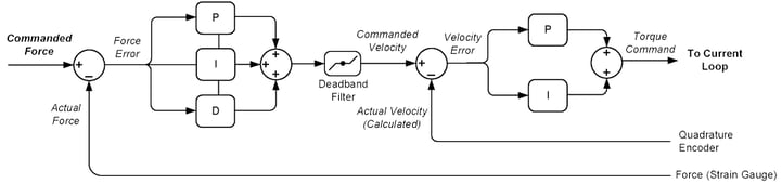
Figure 12: Force Control Loop Using External Strain Gauge
Here, the commanded force command is explicitly combined with the force sensor value and passed through a PID filter. This outer loop then sends a corrective signal to a downstream velocity loop. The motor is commanded forward or backwards on a continual basis to precisely maintain the commanded force.
In the diagram above note the inclusion of a deadband filter, located at the output of the force loop. Deadband filters are useful for reducing hunting when the command velocity or torque is near zero. It is programmed with an upper and lower limit, which when so programmed creates a hysteresis function.
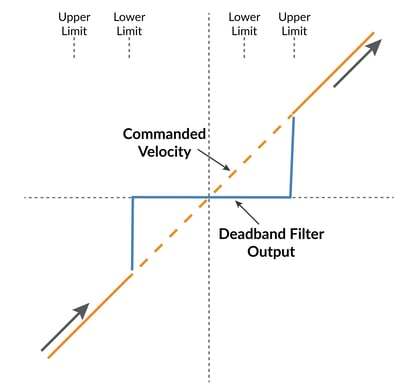
Figure 13: Deadband Filter
You may also be interested in: Servo Motor Tuning – Rocket Science or Walk In the Park?
I sense the body electric
While grippers are a helpful vehicle to talk about force sensing and control, the general use of servo motors to sense the presence of objects and even the nature of objects within the end effector’s motion range leads us to another interesting application for force sensing servo systems – remote teleoperation with force feedback.
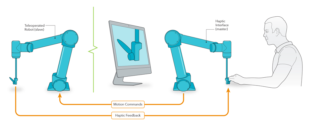
Figure 14: Servo-based Remote Teleoperation Setup
Figure 14 shows the configuration for such a setup. A human operator manipulates some sort of mechanical replica of the servo-actuated device being remotely controlled and in turn receives force feedback information according to the force being ‘felt’ by the remotely operated device. Applications for such a system include robotic surgery, nuclear materials manipulation, underwater robotics, dangerous materials handling, and more.
How does such a system work? As it turns out such a system is essentially a two-directional version of the servo-based force application & sensing discussed in the previous sections of this article. Both the human operator’s mechanism and the remotely operated mechanism have servo control systems that can command motor position & torque and report this information back to its tele-counterpart.
An example illustrates this. In a remote teleoperated system the remote mechanism is unimpeded as it moves in a direction commanded by the operator. The amount of force needed to undertake the move in the remote mechanism is small since there is nothing pushing back. That small amount of force is applied to the teleoperator’s actuation mechanism, which is experienced by the operator as zero, or nearly zero, resistance to the move.
Now imagine the remote mechanism encounters a wall. As the teleoperator continues to push his actuator forward the force output by the remote mechanism’s motor to obey this move will increase rapidly. This force, still being continuously output back to the operator’s actuator will be felt by the operator is an impediment. As they try to push forward, they cannot – their actuator fights back reflecting the force output being sent back by the remote mechanism.
What is interesting and especially powerful about teleoperated mechanisms such as this is that the operator is not only able to feel the presence (or not) of a wall, but subtle gradations of force as well, depending on the physical nature of the object encountered. So the operator can feel the difference between a hard wall, a pliable material, a material that initially has a hard surface layer but then gives way to a softer interior, etc.
Adding to this, because the data flow and servo control systems on both ends of the system are all computer controlled it is possible to arrange for force reduction or multiplication in the system. For example the remote mechanism could be a very small object such as a syringe needle under the control of a ultra-miniature servo motor.
In such a system the operator could feel the needle penetrating objects even as small as a biological cell because the force projected to the operator’s mechanism could be multiplied a thousand or even a million times.
It’s fair to say that development of remote teleoperated mechanisms such as these is still in its infancy. Many of the possible applications are still in the research lab. Other applications though, such as remotely operated surgical robotics, have been commercialized and in use for years.
We’re not in Kansas any more
To close out our discussion of linear actuators, end effectors, and force feedback, we will take a look at the very interesting world of Virtual Motion Systems, known as VMS for short, but also called haptic systems.
Virtual motion systems can be thought of as remote teleoperated systems where instead of a remote mechanism actually interacting with a physical object, the physical object along with the space it resides in is virtual. It exists only in the mind of a programmed computer which simulates the force the user would experience if they (for example) extended their hand, swung a sword, or operated the controls of a simulated airplane.
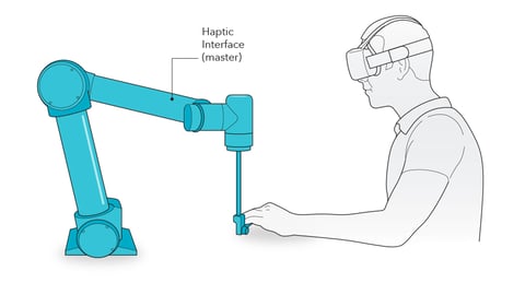
Figure 15: Typical VMS (Virtual Motion System) Setup
The core of such a system is the same. The operator interacts with a servo-based system that can sense the operator’s movements and impart a force that the operator can feel. The mechanical system that the operator interacts with doesn’t necessarily have to match the system being controlled, but does in fact do so for some systems.
The most direct example is a commercial airplane simulator. For these devices the operators sit in a detailed and accurate replica of the airplane cockpit being simulated. When they handle controls which can move during flight such as the steering wheel (known as a yoke) they feel exactly what they would feel in the real world. This can include the effect of inclement weather and all manner of physical real-world conditions experienced by the simulated airplane as it travels on a simulated flight.
In VMS’s that do not have a physical replica of the operating environment the operator often wears a VR helmet capable of projecting a simulated image of the environment being interacted with. An example of such a system might allow users to ‘feel’ the contours of an object such as a molecule. The operator might hold a force feedback joystick in their hands, which in combination with the VR helmet would allow them to explore the contours of the object by ‘touching’ it.
Do you need to buy expensive joysticks or simulators to get a taste of VR motion? No. In fact even a simple single-axis motor controlled with a PID (proportional, integral, derivative) control loop can fool your mind into experiencing something tactile, yet only exists in the mind of a computer.
The figure below shows a setup you can use to experiment with this. The motor should be a DC Brush or Brushless DC type that has an encoder for position feedback, with a dowel attached at the shaft functioning as the handle the user will grip. The motor should have enough power to apply a meaningful amount of force on the dowel.
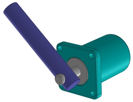
Figure 16: One-Axis VR Motion Experimentation Setup
To experiment with your motion VR system, turn on the motion controller and start with just a setting of Kp (proportional gain). Hold the dowel and twist it and you experience what feels like a simple spring action – the harder you twist the harder the motor fights back. You can make the spring stiffer or looser by increasing or decreasing the Kp value.
So far so good. Next, turn off the Kp, turn on some derivative term, and twist again. The feeling you now experience is that of resistance, as if the dowel is in a bath of molasses. Finally turn on some integral gain. Set the Ki to a relatively low value and Il – the integration limit to a fairly high value. The effect this has on the dowel as you deflect it can be described as a sort-of “oh no you don’t” response. If you get the settings right this increasing application of force by the motor can feel a little eerie, as if alive.
Another notch on your drive belt
These human interpretations of what a simple PID servo loop feels like are interesting, but just the beginning of what is possible. If you have the ability to program your controller, there are many more effects you can create to simulate the feeling of real world objects and interactions.
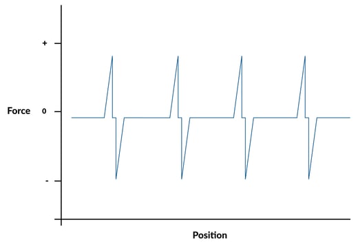
Figure 17: Force Versus Position Map For Notched Selector
One example is a notched rotary selector. Normally this is achieved with a spring mechanism that creates specific click-to spots where the rotary dial prefers to settle.
Can we create a similar system with a servo motor? Absolutely. The trick is creating a position dependent force map as shown in Figure 17. This is commonly done with a direct motor command feedforward term added to the output of the PID (if in fact a PID is even used). As the motor rotates the corresponding output of the encoder is used to determine the torque command lookup value. An alternative approach is to map changes in the PID terms depending on the motor’s rotary position.
Since our entire creation is virtual and stored in the computer it’s easy to change the number of notches, the width and the shape of the notch to change what the selector dial feels like. This flexibility is an inherent advantage of servo-controlled devices such as this. No mechanical re-tooling is needed to change the behavior, just a software change.
You may also be interested in: Feedforward in Motion Control - Vital for Improving Positioning Accuracy
Boink… was that an apple?
Simulated objects can further be given a life of their own by programming the notion of movement and inertia. With such algorithms in place, once the user twists the dowel, after letting go, it continues to spin due to simulated inertia. This is a fun effect to play with and opens the door to the simulated object bouncing against a wall or climbing up a hill, slowing as it loses energy due to ‘gravity’.
The key to making this particular effect work is building an observer that determines what force the user is applying to the dowel, and a software program that simulates the ‘physics’ of the object. First, the force observer - in the basically frictionless system of our VR motor there is essentially no resistance, and so actual position deviations (above a specified threshold to avoid falsely counting the contribution of servo dither) from the commanded position are likely to be due to human application of force to the dowel.
Next, the object movement simulation, which follows Newton’s laws of motion. The force determined by the observer is used to calculate the acceleration on the object using F = ma. The change in the commanded position of the simulated object is then updated using P1 = P0+V0T+1/2AT2 . In other words the basic equation to track the position of an axis which has an existing position (Po), an existing velocity (V0) and an acceleration being applied to it.
Going beyond simulating an object with inertia only, the real world simulator could add the notion of gravity by having the object traverse slopes. As the operator instills motion on the object perhaps it ‘climbs’ uphill requiring more force due to simulated gravity, when the contour is flat there is no extra force needed, and when the object descends a simulated slope the object accelerates on its own due to gravity.
Our example setup used a simple single-axis actuator, but multi-axis systems with more elaborate mechanics are certainly also possible, and in fact already in use. The possibilities are endless for interacting with simulated worlds using a VMS.
Summary
Linear motors form the heart of many robotic and gantry transport system end effectors. While in many cases the goal of the end effector is to control the end move position, an equally common requirement is to control or sense force. Such force-sensing and controlling actuators are used in a wide array of industrial, laboratory, and scientific machinery.
Direct drive servo actuators or actuators with low friction can sense and control force without the need for an external force sensor. Rotary to linear actuators on the other hand often use a strain gauge and a special servo control loop to control force with high precision.
When used in force feedback applications these same end effectors and actuators open the door to Virtual Motion systems that can serve as ultra-realistic flight simulators, remotely operated robot arms, high end gaming consoles, and more.
PMD Products Used To Control End Effectors and Robot Grippers
PMD has been producing ICs that provide advanced motion control of DC Brush and Brushless DC motors for more than twenty-five years. Since that time, we have also embedded these ICs into plug and play modules and boards. While different in packaging, all PMD products are controlled by C-Motion, our easy-to-use motion control language and are ideal for use in medical, laboratory, semiconductor, robotic, and industrial motion control applications.
ION/CME N-Series Digital Drives
N-Series ION Digital Drives combine a single axis Magellan IC and a high performance digital amplifier into an ultra-compact PCB-mountable package. In addition to advanced servo and step motor control, N-Series IONs provide S-curve point to point profiling, field oriented control, downloadable user code, general purpose digital and analog I/O, and much more. With these all-in-one devices building a custom controller board is a snap, requiring you to create just a simple 2 or 4-layer interconnect board.
Learn more >>

Juno Family of ICs
The Juno family of ICs are perfect for building your own low-cost, high-performance controller. Juno's excel at velocity and torque control, with features such as FOC (Field Oriented Control), profile generation, high/low switching amplifier control signal generation, leg current sensing, and more. Available in packages as small as 7mm x 7mm and costing $12 in quantity, these ICs are an ideal solution for your next controller design.
Learn more >>

MC58113 Series ICs
The MC58113 series of ICs are core members of PMD's popular Magellan Motion Control IC Family and provide advanced position control for BLDC, DC Brush, and step motors alike. Standard features include S-curve profiling, FOC (Field Oriented Control), high/low switch signal control, direct encoder & pulse & direction input, and much more. Whether used for laboratory automation, pump control, pointing systems, or general-purpose automation, the MC58113 family of chips are the ideal solution for your next machine design.
Learn more >>
You may also be interested in:
You may also be interested in: Force Control In Actuators ON DEMAND!
- Principles of Motor Selection
- Build vs Buy Of A Three Axis Motion Controller
- Low Cost High Speed Brushless DC Motor Drive
- Introducing ION/CME N-Series Digital Drives On-Demand
- Motion Control Goes Small
- Motion Kinematics
- Feedforward in Motion Control - Vital for Improving Positioning Accuracy