

Everyone working in motion control has a war story; be it the machine that stopped working mysteriously or the motor that wouldn't stop vibrating. This deep dive around motion problems that occur in mobile robotics and portable motion applications is part of a series that focuses on motion control problems you may run into and provides some ammunition to fight the good battle and get your machine design and development project back on track!
Mobile and Portable Automation Demands Light, Efficient, and Cool Operation
In this entry to PMD's solving motion control problems series we will focus on mobile and battery operated applications where three particular requirements become especially important: the weight, the efficiency, and the amount of heat generated by the motor and associated controls.
Mobile robotics covers a broad range of applications, including warehouse robotics, drones, battlefield robots, underwater robots, and more or less any automated mechanism that has to transport itself in its operating environment.
The close cousin of mobile robotics is portable equipment carried or carted by the user. This is typically either medical equipment, such as fluid pumps, drug infusers, and muscle assist devices, or hand held manufacturing and assembly equipment such as drills, torque wrenches, and test probes.
What all of these applications have in common is that they are battery operated. Battery operation drives the need for efficiency, but also the need for less weight since heavier mechanisms will require more energy to move. Lower operating temperature may or may not be important in mobile robots but is often very important in portable equipment applications. This is because excessive heat in the hand held or patient-worn device can cause discomfort or even injury.
So for this entry of our Common Motion Control Problems series, let's go on a diet, get lean and mean, and stay cool as we show you how to improve the performance of your mobile motion controls. We will see that in addition to advances in the motors themselves, there have been a veritable gymnasium of advances in motor controls that are driving an explosion of new applications in mobile motion control and robotics.
Minimizing weight
Every motion control system has two major elements that affect its weight: the motor and the controls that drive that motor. By motor here we mean the entire actuator, so this includes gearheads or other reducers that are part of the actuator assembly, and the weight of any attached encoders or sensors. By controls we mean the electronic system that accepts a DC voltage from the battery, receives or internally executes motion move commands, and ultimately drives the motor coils.
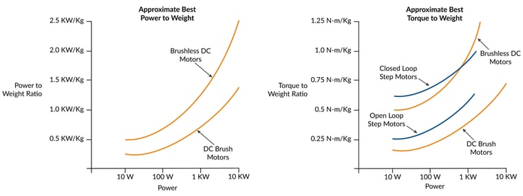
Figure 1: Comparison of Motor Types in Two Key Performance Metrics
First, we will focus on the motor. Figure 1 shows two graphs comparing various motor types in two key performance metrics: power output to weight, and torque output to weight. For a given application usually one of these two factors are more important than the other, and in fact, they are related because power is defined as torque times spin rate.
As the graph shows, Brushless DC motors, with their ability to generate a constant torque up to a high spin rate, typically provide the highest figures of merit for power output to weight. Typical values are double the ratio of DC Brush motors. AC Induction motors, sometimes used in high power applications such as electric vehicles, are only rarely used in mobile robotics so those are not included in these graphs. Step motors, although frequently used in mobile and portable applications, are not usually part of the power to weight conversation because their torque drops off rapidly as rotation speed increases.
If we instead want to optimize torque to weight though, step motors are back on the table. Traditionally open-loop operated step motors have high holding torques, but their ability to deliver that torque over a working speed range is affected by their tendency to oscillate. Practically speaking this means the effective torque delivered by the step motor is between 50% and 70% of the motor's rated holding torque.
There is an alternate way of operating a step motor however which largely solves this issue. A technique called closed loop servo, also called stepper servo, uses an encoder to operate the step motor as if it were a two-phase Brushless DC motor. The result is significantly higher torque over the operating range of the motor because mid-range instability, a torque killer for open loop step motors, is eliminated.
A final note on power to weight and torque to weight ratios is that they generally increase as the motor size and power output increase. While all of the numbers in the graphs above should be taken with a grain of salt, high performance NEMA 17, 23, and 34 Brushless DC motors can achieve power output to weight ratios as high as 1.0 KW/Kg. or higher, but larger motors, for example those that drive electric cars and provide 100 KW of power output or more are now achieving power to weight ratios of 5.0 KW/Kg and higher.
This is for two reasons. The first is the inherent geometry of small motors, which affects how they generate and corral magnetic forces. Motor efficiency sapping effects, such as stray magnetic fields and eddy current generation, are proportionally greater for small motors than for large motors. But another important reason is that motor manufacturers just have not yet been motivated to dramatically increase power and torque to weight ratios for smaller motors.
The electric vehicle market is driving a lot of research activity in this area because it is such a large and economically valuable market to motor manufacturers. Mobile/portable motion control markets, while also growing, are still much smaller. Nevertheless at least some of the design changes that are powering the electric car and even electric airplane markets can be expected to trickle down to the smaller motor market in the next few years.
Closed loop stepper is a game changer
It is worth delving further into a new type of control technique for step motors known as closed loop stepper, also called stepper servo. What makes closed loop stepper powerful is that it can use a standard step motor yet extract more effective torque out of it, particularly over the full range of operating speeds.
So how does closed loop stepper work? Closed loop step motor operation is different in three key ways from regular open loop step motor operation. The first is that it requires an encoder to be attached to the step motor, one with a fairly high resolution. For standard 1.8 degree step motors you will want an encoder with no less than 2,500 counts per mechanical rotation.
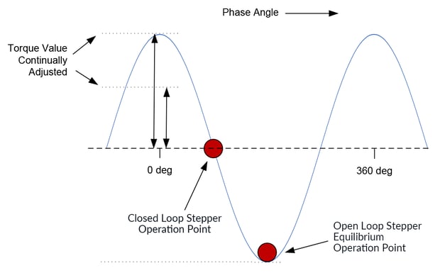
Figure 2: Closed Loop and Open Step Motor Operation Points
The second difference is that closed loop stepper operates the motor like a Brushless DC motor and commutates the phase angle using the actual encoder position. Figure 2 shows the closed loop commutated operation point relative to the traditional open loop operation point. In this figure the steeper the curve, the greater the rotor torque generated.
As can be seen, closed loop stepper runs the motor at the steepest part of the force valley whereas open loop relies on the step motor position to settle to the bottom (the equilibrium point) of the force valley. The result is higher torque and more torque over the operating speed range of the motor with closed loop stepper. This is shown in Figure 3.
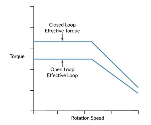
Figure 3: Closed Loop vs Open Loop Step Motor Operation
The third difference is that rather than being constant, the height and sign of the current waveform are continuously adjusted based on the output of a position PID (Proportional, Integral, Derivative) loop. This means closed loop stepper drives the step motor with just enough power to get the job done. Open loop step systems must drive the motor at a power level sufficient to handle the worst case profile and load scenario. The result is that closed loop stepper can drive the motor with much less heat generated.
Many engineers are not yet aware of the closed loop stepper control scheme, but that is starting to change. While not new, in the last few years closed loop stepper has become more attractive as high resolution encoders have become cheaper, and as inexpensive IC-based controllers have come on the scene that make it easy to incorporate closed loop stepper into designs.

You may also be interested in: New Control Technique Combines Servo Performance with Step Motor Cost
Gears and reducers optimize power to weight
When using DC Brush or Brushless DC motors gearheads and other types of reducers can have a big impact on the effective power and torque delivered by the motor system. Power is equal to torque times velocity, so if there is extra velocity available from the motor a gear reducer can be used to increase the torque which in turn increases the power at the desired application velocity.
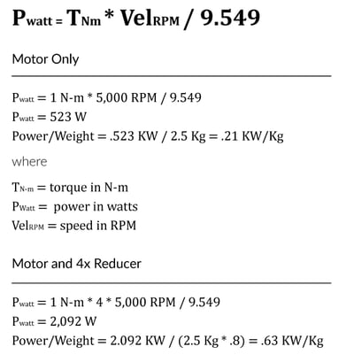
Figure 4: Power to Weight Ratio Calculations For Example Application
The equations in Figure 4 show this. In this example an application has a target operating speed of 5,000 RPM, however the Brushless DC motor to be used is capable of generating 1N-m of torque all the way up to 20,000 RPM. In this application, a 4:1 gearhead will be used to maximize torque.
The motor weighs 2.5 Kg while the four to one reducer weighs .8 kg. The effective power output of the motor by itself at 5,000 RPM is 523 watts, while the output with the gear reducer is 2,092 W. Correspondingly the power to weight ratio goes from .21 KW/Kg to .63 KW/Kg.
On the face of it, this 3 x improvement in power to weight at the target speed looks like a clean win. But as always, the devil is in the details There are potential negative impacts on the motion system that come from reducers including an increase in rotational inertia, reduction in acceleration rate, introduction of compliance and backlash, additional noise, and cost.
One final impact that is made worse by reducers, and which may particularly effect mobile applications, is that motors spinning at high rates act as gyroscopes. Depending on how the robot's direction change aligns with the motor's axis of spin, the spinning motor may introduce mechanical stress on the motor drive train, and in extreme cases the robot may be driven off course or become unstable.
The incredible shrinking motion controller
Figure 5 shows two motion control drives. One was developed in 2010 and has dimensions of 4.3" x 3.0" x 1.5" (109 mm x 76 mm x 38 mm) and weighs 9.3 ozs (264 gms). The other was developed in 2020, measures 1.4" x 1.4" x .65" (37 mm x 37 mm x 17 mm) and weighs 1.15 ozs (33 gms). What is most interesting, however, is that the smaller drive has over a kilowatt of power output, which is twice as much as its larger cousin from 2010.
Figure 5: Reduction in Size of Representative Older Versus Newer Drive
Such is the pace of progress in electronic controls that drive the motor. In fact, increasingly, when embedded motion controls are used - either motion control ICs or modules such as shown in the figure, the contribution of the electronic motion controls to the weight of the overall system almost becomes negligible.
By way of example, borrowing the Brushless DC gear reducer application from earlier, the following table shows the impact of controls on overall system weight. Even for the 2010 technology drive the impact on system weight is about 10%, and for the 2020 technology this drops to just 1.3%.
|
|
2010 Representative Motion Technology Drive
|
2020 Representative Motion Technology Drive
|
|
Power Output
|
500 W
|
>1,000 W
|
|
Dimensions
|
109 x 76 x 38 mm
|
37 x 37 x 17 mm
|
|
Volume
|
315 cc3
|
23 cc3
|
|
Weight of Drive
|
.265 Kg
|
.033 Kg
|
|
Weight of Motor
|
2.5 Kg
|
2.5 Kg
|
|
% of Total Motion Control System Weight
|
10.6%
|
1.3%
|
All of this boils down to "make sure you install state of the art controls". These controls will leverage incredible historical advancements in power MOSFETs (used in switching amplifiers) and size and cost reductions in other components such as CPUs, op-amps, logic circuits, and more.
Wires, network architecture, and weight
Figure 6 shows a traditional and a distributed six axis control system. Even if both systems use state-of-the art motion controls, the connection architecture will have an impact on the weight of the system due to the difference in wiring.
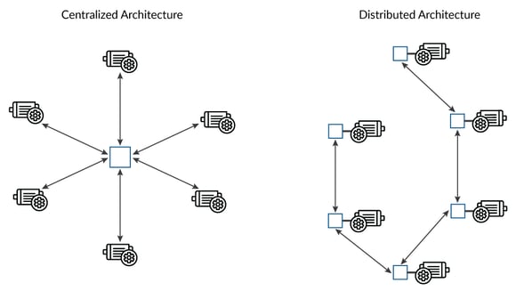
Figure 6: Centralized and Distributed Architecture
A simple example illustrates. Here is an accounting of the wires needed to support a centralized control scheme servicing six motors located in a circle with a radius of .31 m (12") from the center, versus a distributed system servicing the same arrangement. We will assume 3-phase Brushless DC motors along with a Case/Shield wire resulting in the use of four heavier (14 AWG) motor connections per axis, and ten lighter (24 AWG) sensor/ signal wires per axis.
In the distributed system, each drive is assumed to be located at or near the motor and serviced with a two-wire (14-AWG) HV power and a 6-wire (28 AWG) network connection. All other wires such as the heavier connections to the motor coils and the lighter wires to the motor's sensors are assumed to be local and 2" in length.
|
|
Centralized
|
Distributed
|
||
|
|
AWG, Total Length
|
Weight
|
AWG, Total Length
|
Weight
|
|
HV DC Bus Power connections
(2 wires): |
N/A
|
N/A
|
14 AWG, 3.2 m
|
.071 Kg
|
|
CANbus Host Network Connection (6 wires):
|
N/A
|
N/A
|
28 AWG, 9.6 m
|
.011 Kg
|
|
Motor drive connections (4 wires per axis):
|
14 AWG, 7.3 m
|
.163 kg
|
14 AWG, 1.1 m
|
.027 Kg
|
|
Encoder and other signal connections (10 wires per axis):
|
24 AWG, 18.3 m
|
.041 kg
|
24 AWG, 3.0 m
|
.007 Kg
|
|
Total Weight:
|
|
.204 kg
|
|
.116 Kg
|
|
Difference:
|
|
|
|
-.088 Kg
|
This example calculation demonstrates two things: for many systems, the weight of the wiring will exceed the weight of the controls, and a distributed architecture may reduce the weight of the wiring by up to half compared to a centralized system. Nevertheless, as this example also shows the weight of the wiring is just a fraction of the weight of the motor, perhaps 5 to 10% for a typical machine.
There are many factors that go into the decision of whether a centralized or a distributed control scheme should be used. As this example shows the weight of the wires is certainly a valid consideration, but it is only one factor in many to consider when deciding between a centralized and distributed architecture.
You may also be interested in: Motion Controller Design Architectures - A Deep Dive
Time to cool off
With this discussion of reducing weight behind us, it is time to talk about heat generation and the related issue of efficiency. The logical starting place to increase efficiency is at the motor. Brushless DC motors are by far the most efficient type of motor used in typical position and velocity control applications, regularly achieving 90% or higher efficiency particularly for larger motors. DC Brush motors have efficiencies between 60 and 85%, again depending mainly on size.
In the realm of power efficiency step motors operated with traditional open loop control are difficult to compare. For one thing they require energy even when not moving. When operated in closed loop mode however step motors can have their power efficiency meaningfully measured. There is not all that much published information on this, but it is reasonable to assume that their efficiency is in the range of 65% - 75%.
So for many engineers the first place to look to reduce heat and increase efficiency is the motor. All things being equal, for most application, choosing a high efficiency Brushless DC motor will go a long way toward running your system more efficiently.
Check the commutation
With a high efficiency motor now in place, we want to look at various aspects of the control system that can cause less than optimal performance. One such area is commutation misalignment. Misalignment of the commutated electrical angle with the motor's physical angle directly reduces the efficiency with which torque is generated.
While not usually a problem when Hall sensors are used, phase misalignment in Brushless DC motors can be a problem with sinusoidal or FOC control if the phasing was not initialized correctly, or if the encoder is losing counts from time to time. The later condition is common when quadrature encoders are used but can easily be corrected using the motor's Index pulse.
Some simple tests can help diagnose commutation problems. Begin by giving the motor an open loop positive torque command and then a negative torque command. In each case record the steady state speed and compare. The speeds should be equal in magnitude.
Next, run the motor with an open loop torque command at high speed for several minutes or even hours. Record the speed occasionally, noting whether it changes over time. Try this with both positive and negative torque commands. In all cases the velocity of the motor should not change over time.
If any of these open loop motion tests show problems, take a closer look to correct the condition. You may have initialized phasing incorrectly, or you may be experiencing quadrature encoder count losses.
Commutation misalignment can go undetected because the servo loop will happily increase the motor command to compensate for misalignment, masking actual problems until the motor becomes so inefficient at delivering torque that it, or the amplifier, overheats.
Switch to sinusoidal commutation
If your commutation alignment looks OK, you may want to consider switching to sinusoidal commutation. In an apples to apples comparison, Brushless DC motors that are commutated with sinusoidal waveforms are about 5 % more efficient than with traditional six-step Hall-based commutation.
Unfortunately, apples to apples comparisons for a given motor are hard to come by. This is because Brushless DCs are wound to be commutated a certain way. A motor constructed for six-step commutation will actually be less efficient when driven sinusoidally and vice versa. However, it is a certainty that a motor and control system designed for, and driven, by sinusoidal waveforms will outperform six-step commutation.
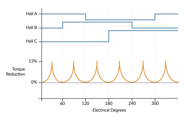
Figure 7: Torque Reduction
Figure 7 shows the reduction of torque and corresponding amount of inefficiency that comes from six step commutation in relation to the phase angle. The worst case value is about 13 %. Averaged over a full rotation this represents a 5 % efficiency loss.
Where does the torque reduction come from? The answer is that Hall sensors only encode six discrete locations per electrical cycle - every 60 electrical deg. In an ideal world, the commutation vector would always be located by the controller exactly 90 deg relative to the rotor's N-S (north south) vector. The fact that instead, the Hall-based controller receives a new update only every 60 degrees, means that other than at the exact Hall update point, the actual vector will be suboptimal. 13% corresponds to the reduction at the locations farthest from the Hall transition points, +/- 30 degrees.
If instead of Hall sensors you use encoder feedback, which usually provides dozens or even hundreds of position updates per electrical cycle, this problem goes away. The motor stator's vector angle can be kept nearly exactly 90 degrees from the N-S vector regardless of the rotor location. That is the basis of sinusoidal commutation. Figure 8 shows waveforms for sinusoidal commutation as well as six-step (also called trapezoidal commutation).
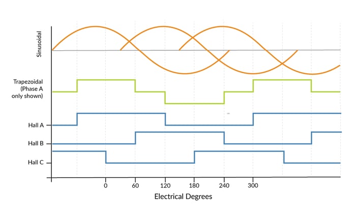
Figure 8: Sinusoidal and Six-step Commutation Waveforms
Use FOC (Field Oriented Control)
Particularly if your Brushless DC motor is spinning at a high rate you should use the FOC (Field Oriented Control) technique for commutation and current control. FOC can deliver a higher top speed, more torque at speed, and lower power consumption at speed. All of these translates to less heat in the motor and in the controls.
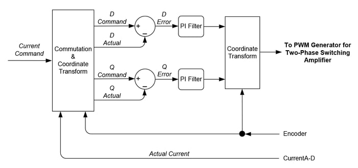
Figure 9: Field Oriented Control Data Flow Diagram
FOC is algorithmically complicated, but by way of high-level summary, works by converting the rotating motor phase frame to a non-rotating coordinate frame, referred to as the D phase current and the Q phase current. The commanded and actual D and Q phase currents are then subtracted and an error generated, which in turn is passed through a PI (proportional, integral) filter. Finally, the output of the D and Q phase PI filters are converted back into the rotating reference frame and output as PWM voltage commands for each phase of the motor.
In the past FOC was a feature that could add cost to the controller and therefore its benefits had to be weighed carefully. Today it is commonplace whenever multi-phase motors such as Brushless DC or step motors spin at a medium to high rate. So, if your application meets those criteria and if you are not presently using FOC you should upgrade to it.
You may also be interested in: Field Oriented Control (FOC) - A Deep
Quiet the chatter by lowering your derivative term
If using a PID controller a high value for the derivative term tends to make the motor chatter and, in the extreme case, draw enough extra energy from the amplifier to impact overall efficiency. To address this try lowering your derivative term in combination with your proportional gain to reduce noise.
If the noise goes away but the servo tracking performance is no longer where you want it to be, perhaps because the system has now become underdamped, consider operating with two sets of servo parameters, an active set and a holding set. Using a less aggressive, less energy intensive holding set may be a good solution since the servo usually does not have to do much work to hold the axis in the same position.
Another servo-related area to look at is the loop speed. Digital servo systems tend to run at very high servo loop rates, much of which is not needed in the average application. Higher servo loop rates can excite more resonances in the system and generally result in more servo hunting and chatter.
So, investigate whether changing the servo loop time, or the derivative sampling time if it can be adjusted, reduces chatter and noise. Ultimately, if the motor is generating noise the energy needed to create that noise is wasted. So, while not entirely scientific, noise reduction can be an effective way to inch up the motor drive efficiency.
You may also be interested in: Servo Noise and How To Fix It
Increase the PWM frequency or add an inductor
Another source of chatter and heat generation in the motor occurs when there is too much current ripple coming out of the switching amplifier. Modern motors seem to be trending towards lower and lower inductances because this allows them to spin and accelerate faster. In the past, a PWM frequency of 20 kHz may have been common for a typical small motor such as a NEMA 23, but today PWM frequencies of 40 kHz, 80 kHz, or even higher are often needed to correctly control these motors.
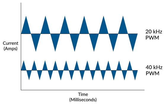
Figure 10: Current Ripple
How does PWM frequency impact efficiency? The answer is that a digital switching amplifier delivers extraneous energy in a saw tooth pattern for a given current command. Increasing the PWM frequency reduces the magnitude of this noise inducing and heat-generating current flow, and improves the accuracy of the current measurement. The figure above shows comparable 20 and 40 kHz current waveforms, although the exact form of the saw tooth will depend on the current command and motor coil inductance.
Increasing the PWM frequency will somewhat decrease your switching amplifier's efficiency, so an alternative is to put an inductor in series with the motor coils. This may not always be possible especially for high speed applications, but an inductor will smooth out the current ripple by lowering the rate at which the current can increase or decrease. Of course, inductors have weight, so this will also affect your analysis of their pros and cons of adding an inductor.
Consider a deadband filter
A special type of filter that can be quite effective at reducing chatter and noise, and therefore reduce extraneous energy-eating movement, is called a deadband filter. Used in either the current loop to limit integral, or the position loop, this technique tells the servo loop not to worry about small amounts of windup, or small amounts of position error, and to only kick in for larger corrections. This has the effect of reducing the number of small corrective commands.
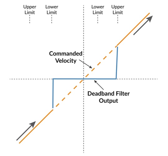
Figure 11: Deadband Filter Function Diagram
Figure 11 shows a general purpose response curve for a deadband filter, which utilizes programmable lower and upper limits to establish the engage and disengage points of the filter hysteresis. If you end up using a deadband filter in your control system, make sure you test it out over the range of loads and operating conditions your system will experience. You want to ensure that the applied values achieve the desired effect over the full projected lifetime and application space of the machine you are designing.
Recharge the battery using regeneration
Finally, for applications involving mobile robots that may become net generators when they decelerate or coast downhill, the controller can recapture that energy and recharge the battery. The reason the motor becomes a generator is that the back-EMF (electro-motive-force), which increases linearly with rotation speed of the motor, eventually exceeds the supply voltage. When that occurs the direction of current flow from the HV supply, which is normally towards the drive, reverses and heads back to the supply.
Whether or not this excess voltage is used to regenerate the battery, if not handled it can cause serious damage to the power supply, the motion control electronics, or the motor. Two alternate approaches to handling this condition include charging a power capacitor and operating a shunt resistor.
While recharging the battery sounds like the perfect solution, the circuitry to monitor and execute this is not trivial. If the motor becoming a generator is a rare event, or if the total amount of energy associated with this occurrence will not meaningfully impact battery life, implementing one of the two alternate approaches mentioned above may be preferred.
Summary
Mobile and portable motion applications are exploding in popularity due to the continual reduction in the size of the electronics and in the cost of electronics such as CPUs, FPGAs, and analog processing.
Although high power motors used in electric cars and industrial applications have made major improvements in power to weight ratio, smaller motors have also made meaningful improvements in this area. In the future we can expect to see further progress as manufacturers create specialized motor drives to address the mobile and portable motion control markets.
Even with today's motors there are a number of controls techniques that can optimize efficiency and minimize heat generation including FOC (Field Oriented Control), filters such as dead band filters, and regeneration.
PMD Products Used In Mobile & Portable Motion Applications
PMD has been producing ICs that provide advanced motion control of DC Brush and Brushless DC motors for more than twenty-five years. Since that time, we have also embedded these ICs into plug and play modules and motion control boards. While different in packaging, all of these products are controlled by C-Motion, PMD's easy to use motion control language and are ideal for use in medical, laboratory, semiconductor, robotic, and industrial motion control applications.

Magellan & Juno Motion Control ICs
Magellan and Juno Motion Control ICs are perfect for building your own control board and achieving the smallest, lightest per axis controls. They feature the latest in servo motor control techniques including PID with feedforward, biquad filtering, current control with FOC, and PWM (Pulse Width Modulation) at up to 120 kHz. Magellan ICs are PMD's world-leading solution for positioning motion control, while the Juno products represent PMD's latest generation of high performance, low cost velocity & torque control ICs.
Learn more >>
ION Digital Drives
ION Digital Drives combine a single axis Magellan IC and an ultra-efficient digital amplifier into a compact rugged package. In addition to advanced servo motor control, IONs provide S-curve point to point moves, i2T power management, downloadable user code, and a range of safety functions including over current, over voltage, and over temperature detect. IONs are easy to use plug and play devices that will get your application up and running in a snap.
Learn more >>

Pro-Motion Analysis Software
Pro-Motion is PMD's easy-to-use Windows-based exerciser and motion analysis program. It offers ready-to-go capabilities your entire development team will be able to share. A step-by-step axis wizard allows designers to quickly and easily tune position loop, current loop, and field-oriented control motor parameters. Advanced users can access a complete motion analysis package with Bode plot generation and auto-tuning.
Learn more >>
More in this series:
You may also be interested in:
- Precision Fluid Handling: It's All In The Pump
- Precision Fluid Handling: Taking Lab Automation To The Next Level
- Advanced Motion Control of Servo and Step Motors
- S-Curve Motion Profiles - Vital For Optimizing Machine Performance
- Improving Liquid Handling Pumping Through Optimized Feedback