
Once the decision is made to use an electric motor to control motion in a new machine design, one or more project engineers will be assigned to selecting a motor for each axis of the machine. Where will they start this process?
Requirements
They are likely dealing with two major categories of system requirements.
- Speed/Torque characteristics (mechanical power and bandwidth)
- Kinematic Accuracy (position, velocity)
When the Speed/Torque requirements are known, the selection of a motor to meet those requirements becomes more deterministic as the servo motor vendor should provide “speed/torque” curves and the step motor vendor should, at a minimum, provide maximum torque and a maximum speed. All of these assume the use of the nominal motor voltage.
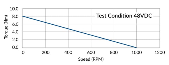
Figure 1: Example Speed/Torque Curve
What is absent from the speed/torque curve is a characterization of the motor’s second order response (inertial acceleration) with or without loading. The inertial properties of the motor’s rotor should be specified in the data sheet and can be used, in conjunction with the inertial properties of the load, to calculate a system level mechanical bandwidth.
In many cases the system power and accuracy requirements are not truly known until a prototype mechanical assembly is available. Motor selection could follow one of two paths:
- Rely on tribal knowledge of motors used in legacy machines of equivalent functionality.
- Oversize the motor during prototyping and downsize when requirements are known.
Selecting the right motor
There are many types of electric motors which can be used to control motion. This discussion will begin with the two major categories, step and servo, and the effects of choosing one versus the other.
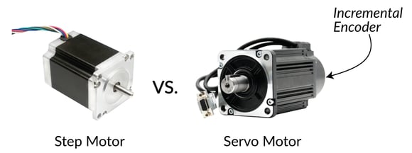
Figure 2: Step Motor vs Servo Motor
Step motors
In the context of cost minimization, the open loop step motor is the first choice. However, the aforementioned requirements may eliminate the possibility of using a step motor with open loop control.
- The maximum speed of a step motor is limited due to the high number of pole pairs.
- The accuracy of an open loop step motor is dominated by the system loading as a proportion of the step motor’s torque rating.
Expanding on the topic of step motor accuracy, when the system loading is 10% of the rated torque and at rest, the positional error is approximately ¼ of a whole step (0.5 mechanical degrees). At a smaller scale there are many properties of step motors which effect accuracy such as construction which controls the geometry of the magnetic flux field. There is a fair assumption made that the step motor controller is regulating the motor current in an ideal way. Typical deviation in the current regulation will be insignificant in comparison to the errors discussed above.
You may also be interested in: Digital Current Loop Significantly Quiets Step Motor Noise
Before discussing servos motors, in most applications there will be another requirement related to maximum motor size since space is usually limited. In cases where the motor will be in motion, motor weight also becomes significant, and to a lesser degree mobility and shipping considerations may be important regarding motor weight. Here is where the step motor has an advantage: due to its high pole count the torque “density” increases. This means, generally speaking, a step motor of a given size can produce more torque than a servo motor of the same size.
Servo motors
Excluding any requirements related to torque density, the servo motor has the best chance of meeting the two primary requirements listed above. A 3-phase brushless motor with one pole pair will offer the fastest maximum speed. The highest speed applications (above 5,000 RPM) are typically rotating a balanced inertia without any external loading, for example, a centrifuge. Some of the highest speed brushless motors are optimized for rotation in one direction. The axis of rotation will likely be vertical resulting in an initial axial bearing load (gravity). Producing a perfectly balanced system is not possible and as the system accelerates, radial forces will replace axial forces as the dominant bearing load. The speed at which this process happens is proportional to system eccentricity. A portion of the torque required to accelerate is used for inertial acceleration which is deterministic and can be estimated from a model. However, generating a model of the radial bearing forces will prove difficult as friction and worst-case eccentricity are likely unknown during this stage. The full scope of torque requirements will not be known until a prototype can be tested.
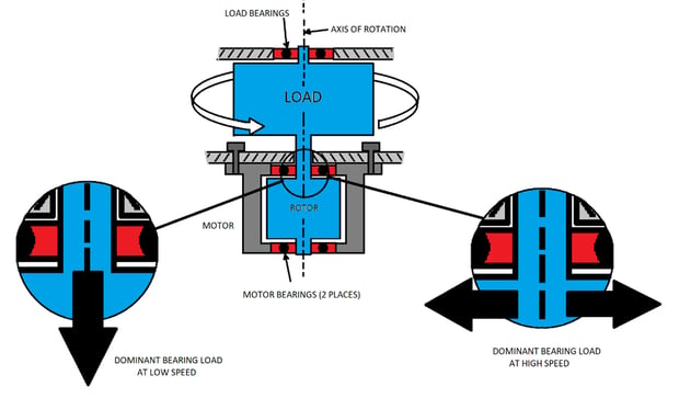
Figure 3: Centrifuge - Non-deterministic Torque Requirement
In juxtaposition is a servo motor used to control a joint in an articulating robot arm for vehicle assembly. This motor is continuously accelerating and decelerating a large, unbalanced inertia. Bearing friction is still present however inertial properties will dominate the motor torque demand which is required for joint acceleration. If a model of the robot/load system exists with an accurate representation of inertial and kinematic properties, the motor torque requirements can be estimated.
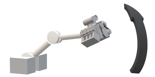
Figure 4: Robotic Arm - Deterministic Torque Requirement
In terms of accuracy requirements, the servo motor with position feedback is the obvious choice. In most cases a servo system can settle to within +/- 10 encoders counts when at rest. The primary concern then becomes selecting an encoder with a positional resolution that is 10 to 20 times the accuracy requirement. Many systems have the encoder attached to the “load” as opposed to the motor and some have one encoder on each. Reference “Dual Position Loop” in link below.
You may also be interested in: Common Motion Problems and How to Fix Them - Part III
The servo motor’s response, or the mechanical response of the system as a whole, is also critical to accuracy. Ideally the kinematic response of the motor/system is linear with torque. Static friction makes a linear response impossible when starting and stopping a move, therefore high accuracy systems involve mechanics designed to minimize static friction and optimize linearity. At the nanometer scale these are systems like microscopy stages which employ the use of linear motors. A 3-phase linear motor can be envisioned as a 3-phase BLDC motor which has been “unwrapped” where the magnetics are stacked end to end. The magnet stack may be located below the windings (stationary) or above the motor windings (moving platform). The latter improves the robustness of cabling which will not flex during motion nor will it apply a force to the platform. However, extending the range of motion requires extending the winding configuration which is more complicated compared to simply adding magnets to the stack. Either way variable flux generated by the motor coil current interacts with the magnets resulting in motion along the track. A voice coil is an example of a single-phase linear motor which are commonly used as the focusing axis of a microscopy stage which again has minimal friction and a linear response. Note the mechanics of these high accuracy systems are delicate and require some type of vibration isolation to meet the strictest requirements.
Size and shape
The National Electrical Manufacturer’s Association (NEMA) has provided the mechanical engineer with a standard for defining the dimensionality of the motor’s face, shaft, and mounting holes. The various NEMA motor sizes (NEMA 8, 11, 14, 16, 17, 23, 24, 34, 42) are in reference to the length of one side of the motor face in units of 1/10 of an inch. The motor manufacturer is left with significant freedom for designing the interior construction of the motor as well as the motor’s length. As a result, the power/torque ratings within a given NEMA size can vary by 10x.
Many vendors do not adhere to this standard and in many cases would be impossible due to the motor’s construction. Requiring the candidate motor to adhere to a NEMA standard is probably too limiting but should be considered in the context of sourcing multiple motor vendors. When using a direct drive system, the options for motor orientation and location may be extremely limited. The standard motor geometry may not be suitable. For example, if the motor length is restricted and room exists for a large motor diameter, using a “pancake” motor may be suitable.
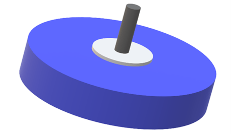
Figure 5: Pancake (flat) Servo Motor
Another mechanical solution under the category of brushless DC Motors is a hollow shaft motor which many times is also frameless. As the name implies, the hollow shaft allows mechanical components to be placed in the geometric center of the motor. A frameless motor (only rotor and stator supplied) expands options for mechanical solutions which include using dual concentric motors to increase torque and locating the motor very close to the load to reduce coupling inefficiencies.
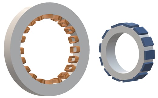
Figure 6: Hollow Shaft Frameless Motor
Bearings
The centrifuge application mentioned above describes a case where both axial and radial bearing loads exist. As with most bearings, a motor bearing’s maximum axial and radial loading should be specified in the motor data sheet and some motors are tailored for one or the other. For obvious reasons the bearing load should stay within tolerance to prevent mechanical failure.
Gearing
Various types of gearing mechanics exist which include a broad field of mechanisms such as lead screws, belts, rack and pinons, bevel and worm gears. These are gear “reduction” assemblies meaning the speed is reduced and the torque is increased. In terms of integrating the mechanism into the rotary motor assembly, the planetary gear offers a unique solution. The available torque can be dramatically increased and only the effective length of the motor and weight is increased. The unique mechanical configuration of the planetary gear assembly allows for coupling to the motor without affecting the “face” dimensions of the motor assembly and makes it possible to maintain adherence to NEMA dimensional standards.
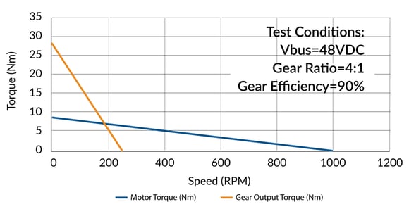
Figure 7: Example Speed/Torque Curve with Gearing Assembly
The gear ratio (in this case 4:1) is an effective torque multiplier. The gear assembly efficiency is also used in the final torque calculation. The resulting available torque will be increased by a factor of the gear ratio times the efficiency. The maximum speed will be decreased by the same ratio. For small ratios like 4:1 an efficiency of 90% is possible. For assemblies with large ratios and multiple mechanical stages the efficiency can drop below 50%.
Slotless brushless motors
The legacy brushless motor is constructed by wrapping the stator coils around the “teeth” of an iron structure which maintains the geometry of the wire coils and subsequently induced magnetic field. This construction creates gaps between the coils which results in a distortion of the field as the rotor magnets move across the gap. The field distortion will affect the torque the motor produces for a given current. This can be problematic for slow speed applications where momentum is not available to smooth or filter the distortion.
A slotless motor is an alternative construction which bundles the coils together and avoids wrapping them around a structure. This eliminates the gaps between coils and the resulting field distortion. The torque to current proportionality is now constant irrespective of motor position. Unfortunately, this improvement does come at the cost of reducing the maximum torque and speed.
Axial flux motor
Most motors fall under the category of radial flux motors. Meaning the orientation of the magnetic flux is perpendicular to the motor axle and the rotor rotates inside the stator. An axial flux motor re-orients the windings and magnetics such the magnetic flux is now parallel to the motor axle. The windings and magnets are stacked side by side along the length of the motor. In a radial flux motor, the wires on the outer diameter of the coil have little significance in terms of creating magnetic flux. In an axial flux motor, all wires in the coil contribute to creating magnetic flux. This creates a significant advantage in terms of higher torque density.
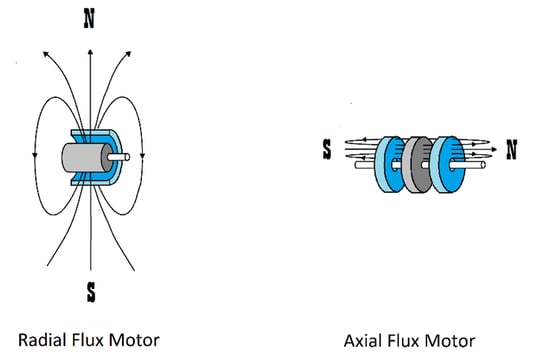
Figure 8: Motor Flux Orientation
The principle of the axial flux motor is not new compared to the radial flux motor but had been historically hindered due to manufacturability. Production of any motor is a complicated process. The production of an axial flux motor is especially complicated which is why they are less common. In all cases a gap is required between the rotor and stator. Axial flux implies the gaps are radial which results in a larger bending moment. This increases material stress and increases the difficulty of maintaining the gap tolerance. However, thanks to the increased demand for electric motors in transportation applications such as drones, warehouse robots, and electric vehicles, improvements to the design of the axial motor have been made. They are now an irreplaceable component in many high torque applications.
Often the packaging of the axial motor will be flat and may be referred to as a pancake or disc motor. Axial flux and radial flux motors exists in both standard and pancake (flat) form factors. However, the geometry of the axial flux motor lends itself more readily to a flat motor design.
Inertial matching
Regarding common practices for motor selection, the concept of inertial matching has existed in the industry for many decades. The most basic interpretation is to select a motor whose rotor’s moment of inertia (Jm) is close to the load’s moment of inertia (Jl). This implies the load to motor inertia ratio is approximately 1:1. Of course any effort made to match inertia will be useless if the resulting motor does not meet the previously mentioned torque/speed requirements. However, with modern motors, it will likely be possible to have a large inertia ratio (Jl ≫ Jm) and still meet those requirements. Along those lines if the ratio is closer to one (i.e. larger motor), there is all the more reason to believe those requirements can be met.
Selecting a motor which results in a large inertia ratio can appear to be advantageous in the context of reducing size and weight. However, there are likely disadvantages. One being an increase in electrical power and another less obvious disadvantage is an increased tendency for system instability. The effects of the latter are dominated by the mechanical compliance between the motor and load. The frequency where resonance begins will be dominated by the combined effect of load inertia and compliance. When little compliance is present (stiff mechanics) the effects of a large inertia ratio are mitigated since resonance occurs at higher frequencies. Beyond the resonant frequency “inertial-reduction instability” can occur where the motor can oscillate as if no load is attached (i.e. the inertial load has been reduced to zero) [1]. In this case the load is effectively at rest and all mechanical power is going into the kinetic energy of the motor’s rotor. The motor response (and subsequent feedback response) increases at those higher frequencies and the effect is exacerbated by a larger inertia ratio. In summary, a large inertia ratio increases the probability of instability.
Choosing an inertia ratio of less than one ( Jl < Jm) will further reduce the tendency for inertial-reduction instability. As demonstrated in the table below, there is evidence that the highest bandwidth applications will in fact minimize this ratio. This is done at the sacrifice of increasing the size and weight of the motor and the possibility of selecting a motor which is overpowered for the application.
The discussion above has simplified the mechanical load into a rotating inertia coupled to the motor with a compliant (elastic) mechanism. Only in the case of a direct drive system would this simplification be representative of the actual mechanics. In many cases the rotary motion of the motor needs to be translated into linear motion which will introduce additional components such as a belt or lead screw, or maybe gearing is introduced to increase torque. In this case the inertia of the load “felt” by the motor has been altered compared to the direct drive case. The loading on the motor is sometimes referred to as the “reflected” or “apparent” inertia. In the context of the inertial matching analysis, the apparent load will be substituted for the real load inertia (J(reflected_load):Jm). Note that the addition of gearing to a system will be driven by torque requirements, not inertial matching.
In general motor selection can optimize cost, weight, and efficiency by selecting an inertia ratio greater than five, however, this becomes less feasible as the system bandwidth requirements increase. This is demonstrated in the table below:
| Application | Inertia Ratio Jl/Jm |
| Direct Drive/Minimal Compliance | >100 |
| Damped | >5 |
| Typical Servo | 3-5 |
| Responsive | 1 |
| High Bandwidth | 0.70 |
*Information from Reference [1]
[1] Ellis, George (2012). Control System Design Guide. Kollmorgen Press, 358.
Summary
The truth about motor selection is that there isn’t, at least yet a perfect motor for all applications. Motor choice may be affected by a number of parameters including the mechanical characteristics of the control application, tolerance for noise, desired speed range, and cost.
To help you select the best motor for your application, the following chart summarizes what motors provide which advantages:
| Desired Characteristic | Favors Use Of | Comments |
| Low cost | Step motor or DC Brush | Brushless DC motor costs are coming down but are still well above low-end step motor or DC brush motor costs. |
| Smooth operation (minimal noise or vibration) | DC Brush or Brushless DC | Brushless DC motors can be smoother using high-performance commutation techniques such as sinusoidal commutation. |
| High speed operation | Brushless DC | Step motors are not generally suitable for applications beyond 5,000 RPM. |
| High torque to size ratio | Step motors and Axial Flux motor | Step motors provide high torque at relatively low speed only. |
| Ease of use | Step motor | No feedback required and no servo tuning. |
Before starting a motion control project try to determine your system’s requirements as a whole, factoring in the cost of the motor as well as the control system. Also, don't forget to factor in your own comfort level working with more complex technologies such as PID/servo control and external commutation.
PMD Products That Provide High-performance Motor Control
PMD has been producing ICs, drives and boards that provide advanced motion control of Brushless DC, DC Brush and step motors for more than thirty years. While different in packaging, all PMD products are controlled by C-Motion, our easy-to-use motion control language and are ideal for use in medical, laboratory, semiconductor, robotic, and industrial motion control applications.
ION/CME N-Series Digital Drives
N-Series ION Digital Drives combine a single axis Magellan IC and a high performance digital amplifier into an ultra-compact PCB-mountable package. In addition to advanced servo and step motor control, N-Series IONs provide S-curve point to point profiling, field oriented control, downloadable user code, general purpose digital and analog I/O, and much more. With these all-in-one devices building a custom controller board is a snap, requiring you to create just a simple 2 or 4-layer interconnect board.
Learn more >>

Juno Family of ICs
The Juno family of ICs are perfect for building your own low-cost, high-performance controller. Juno's excel at velocity and torque control, with features such as FOC (Field Oriented Control), profile generation, high/low switching amplifier control signal generation, leg current sensing, and more. Available in packages as small as 7mm x 7mm and costing $12 in quantity, these ICs are an ideal solution for your next controller design.
Learn more >>

MC58113 Motion Control IC
PMD's MC58113 IC provides advanced single axis position control for BLDC, DC Brush, and step motors alike. Standard features include s-curve profiling, programmable breakpoints, two axes of encoder input, FOC (Field Oriented Control), intelligent performance trace, and more. The MC58113 family of ICs are the ideal solution for your next positioning application challenge.
Learn more >>
You may also be interested in:
- Build vs Buy Of A Three Axis Motion Controller
- New Control Technique Combines Servo Performance With Step Motor Cost
- Motion Control Goes Small
- S-Curves Profiles - A Deep Dive
- Motion Kinematics
- Feedforward in Motion Control - Vital for Improving Positioning Accuracy