Instead of wasting the potential energy associated with the BackEMF voltage of a vehicle's electric motor via heat loss, it can be used to recharge the battery and therefore recover energy for higher system efficiency. Certain manufacturing processes can be made more efficient in similar ways. See diagrams, graphics, and equations.
In the motion control industry, the term “regeneration” or “regenerative braking” refers to using the power associated with the BackEMF (back electromotive force) voltage of an electric motor to charge a battery. This is the opposite of the normal operational mode where the battery is used to provide power to an electric motor. However, since an electric motor can act as a generator, a system can be designed where the power flow (in or out) of the motor and battery can change in real time. So, instead of throwing away the BackEMF power into heat loss, it can be used to recharge the battery, thereby recovering energy, adding to overall system efficiency. See Figure 1 below.

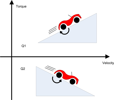
Figure 1: Two of Four Quadrants
Gravity Testing
Many motor/battery systems have the potential for regeneration, this deep-dive will investigate the specific case of a battery powered vehicle using a permanent magnet motor as the drive. This system is simple and has an intrinsic steady state regeneration condition (until the bottom of the hill is reached). The drive system will operate in all “four quadrants”, meaning the drive must be able to control both the acceleration and deceleration of the vehicle in both forward and reverse. At steady state there exists the possibility to use the motor's BackEMF voltage to re-charge the battery in two of the four quadrants. Under the right conditions this can make a significant contribution to the system's power efficiency in the context of extending the time between battery charges.
Figure 1 shows the vehicle operating in two of the four quadrants, one being positive velocity/ positive torque, the other being positive velocity/ negative torque. The other two quadrants can be easily realized by reversing the sign of velocity. The direction of rotation of the motor will determine the sign of the motor’s BackEMF voltage and the magnitude of the velocity will determine the magnitude of the motor’s BackEMF voltage.
In Figure 1, the motor’s BackEMF voltage is always positive and increases in magnitude with speed. It is assumed that the vehicle moving uphill will always need a “positive” torque as indicated by the direction of the arrow. The vehicle moving downhill requires a “negative” torque from the motor in order to brake the car and prevent a run away condition.
Motor Model
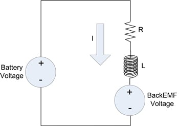
Figure 2 demonstrates the standard single phase motor model (resistive, inductive, and BackEMF components) whereby positive current flow corresponds to motor torque in the positive direction. The polarity relationship between the battery voltage and motor's BackEMF voltage stem from that current flow convention (the polarity of the motor's BackEMF voltage is rotation direction dependant and will oppose the direction of current flow that generates torque in the same direction).

Figure 2: Motor Model Sign Convention
Control of the vehicle under the given conditions requires proportional control of the current in the motor. This is achieved by utilizing a voltage regulation scheme that can apply a portion of the battery voltage to the motor with either positive or negative polarity. This proportional voltage is referred to as an “effective voltage” (Veff). This concept is the foundation for common servo motor drives (linear and PWM switching) where proportional control is required. The effective voltage, along with the motor components, is used in the standard electrical motor equation which can be derived from Figure 2 after substituting effective voltage for the battery voltage.
Veff = Ri + L(di/dt) + Vemf
Where Does Regeneration Live?
All points in quadrant #2 (see Figure 1) correspond to a condition referred to as “dynamic braking”. The motor current is producing torque in the direction that opposes motion (hence the “brakes” are being applied). The emotive force behind that current could be the battery or the BackEMF and, in almost all of cases, is a result of both.
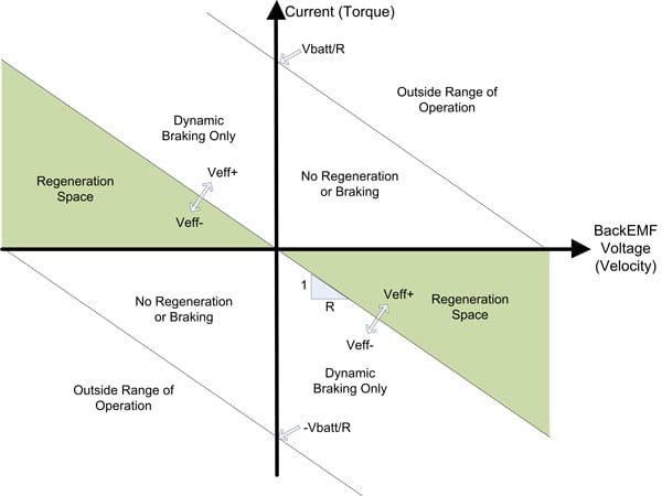
For the steady state condition, quadrant #2 can be further divided based on the sign of the effective voltage, Veff, which is determined by the controller to yield a specific motor current. The region in quadrant #2, where the effective voltage is positive (opposing the BackEMF), is where “regenerative” braking takes place (not just “dynamic“ braking). Refer to Figure 3 for an illustration of this. In the case of transient operation, regeneration can occur anywhere within the operating range.

Figure 3: Steady State Regions of Operation
This is also the one and only steady state region where current is flowing into the positive terminal of the battery. Assuming the duration of time spent in this region is significant, this condition equates to electrical power flow into the battery and hence the battery is “re-charging”. In the given system, the path of energy exchange begins with gravitational energy (elevation change) conversion into kinetic energy which includes the rotational energy of the vehicle’s wheels. The wheel rotation translates into a motor rotation and subsequent BackEMF voltage which, under specific conditions, results in current flow into the positive battery terminal.
Up until now the left hand side of Figure 3 has not been discussed. In this half, the velocity is negative and therefore, the BackEMF voltage is also negative. The polarity relationship between BackEMF voltage and effective voltage is preserved. In the case of negative BackEMF voltage, the effective voltage must also be negative and the current must be positive in order for regeneration to occur at a steady state.
Figure 3 was derived for the given system but is valid for simple inertial systems driven by a motor operating at steady state. In other systems, external forces could alter the location of the operational envelope defined there.
H-Bridge Analysis
An H-Bridge is the most common scheme used to implement a four-quadrant PWM controller on a Brushed DC servo motor. The PWM duty cycle controls the proportion of the supply voltage (battery) that the motor is exposed to, which has been previously referred to as the effective voltage.
A steady state analysis will be performed at a point in the positive velocity regeneration region. The motor winding current at steady state can be expressed in terms of effective voltage, BackEMF voltage and winding resistance.
Iss = (Veff - Vemf)/R
The steady state selection point results in the following requirements:
- Veff > 0
- Vemf > 0
- Vemf > Veff
- Vbatt > Vemf + RI
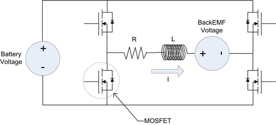
A motor controller will control the effective voltage to the motor by controlling the four MOSFETs of the H Bridge shown in Figure 4.

Figure 4: H-Bridge Drive Stage
Various switching schemes exist for controlling the four MOSFETs, one of which will be employed here. We now join the PWM cycle with the system at a steady state with an average negative current (opposite the direction shown in Figure 4), positive BackEMF voltage, and positive effective voltage. Looking inside the PWM period there are four MOSFET drive states occurring over one PWM cycle in this order:
-
Hi Sides Off / Low Sides On
The current is re-circulating in the lower MOSFETs. The BackEMF voltage causes the current to become more negative as the inductive energy stored in the motor windings is resistively dissipated. There is no flow to/from the battery and therefore no regeneration. The current will decrease at a rate of:di/dt = (-Vemf - Ri)/L
-
Opposing MOSFETs On
Which pair of the MOSFETs depends on the sign of the effective voltage the controller wishes to apply. In this case (+Veff), the upper left and lower right MOSFETs will be conducting. Since the remaining MOSFETs are not conducting, there is only one path for this negative current, which is back into the battery. The current will drift toward zero while energy is being dissipated in the resistive components as well as flowing into the battery. This is a state of regeneration and the battery is being charged. The current will decay at a rate of:di/dt = (Vbatt - Vemf - Ri)/L
Note: Vbatt is the true battery voltage, not to be confused with effective voltage (Veff)
To simplify this proof, the battery is treated as an ideal power source with infinite current sink/source properties.
-
Hi Sides On / Low Sides Off
Identical to the first state with the exception that the current is re-circulating in the upper MOSFETs. -
Opposing MOSFETs On
Identical to state #2, another case where regeneration is taking place. At the end of this state the PWM cycle has completed. Since a steady state system has been defined, the instantaneous current will be equal to the instantaneous current at the beginning of state 1.
We have seen that in states #2 and #4, current is flowing into the battery. There are no conditions where current is flowing out of the battery in this analysis. The instantaneous power delivered to the battery is the battery voltage times the current. However, if the controller was applying an effective voltage which was 25% of the battery voltage, the combined times of states #2 plus #4 would equal 25% of the total PWM period. So, the average power delivered to the battery will be the battery voltage times the current times the duty cycle percentage.
To learn more, read Part 2 - Regeneration Power Modeling
Written by:
Thomas Keller
Senior Applications Engineer
Performance Motion Devices, Inc.

