At a high level, there are four possible stepper motor control architectures:
- Open loop step motor
- Step motor with encoder
- Closed loop stepper motor
- Sensorless step motor
In this article, we will look at each advanced stepper motor control design option and provide an in-depth review of a closed loop motion control system.
1. Open loop step motor
There is no position feedback and the motor is generally over-sized to ensure that it will always overcome the torque requirements. However, you cannot positively know that the motor actually got to the desired position.

Figure 1. Open loop step motor
2. Step motor with encoder
The encoder ensures that the controller can verify that the motor is in the desired position. If not, the motor controller can adjust by providing additional steps, either in real-time during the move when position errors are detected, or post move. This allows the motor size to be reduced as the encoder gives a positive indication of a position problem.

Figure 2. Step motor with encoder
3. Closed loop stepper motor
The encoder is used as a feedback source in a position loop which adjusts the torque requirements in real time. The encoder is also being used in a current loop to determine the proper electrical angle to apply to the motor. Common names for this architecture include “closed loop stepper” control or “servo stepper”.
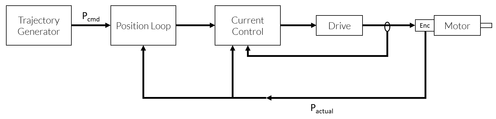
Figure 3. Closed loop stepper motor
4. Sensorless step motor
This architecture does not employ an encoder but instead attempts to derive the rotor location by others means. Various techniques exist such as detecting BackEMF voltage on a passive phase or measuring current rise times. However, there is still no guarantee that the motor is actually at the proper position. In the context of mission critical applications this may not provide adequate knowledge about the motor’s position.
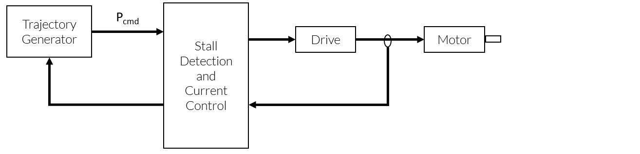
Figure 4. Sensorless step motor
Typical step motor architectures (open loop) drive the motor with a constant winding current without regard to loading or true motor position. (Figures 1 and 2). In the case of the open loop step motor (Figure 1) there is no guarantee that the motor will be close to the target position (large position error) without the presence of position feedback. Of course, encoderless stall detection technologies exist that purport to overcome this lack of information (Figure 4), however they do not monitor actual step motor position. Plus, encoderless stall detection techniques are notoriously difficult to implement since dependencies exist on both the minimum speed required for this technique to work and on the load on the motor (which can be dynamic). In a typical stepper motor, the position error is proportional to the loading which will be dominated by friction at steady state speeds and dominated by inertia during acceleration and deceleration. However, over time and with dynamic load conditions, this situation can change due to aging of belts, bearings and other secondary effects.
|
Open Loop Step Motor |
Open Loop Step Motor with Encoder |
Closed Loop Stepper Motor |
Sensorless Step Motor |
|
| Position Loop |
No |
No |
Yes |
No |
| Current Loop |
No |
Yes |
Yes |
Yes |
| Encoder |
No |
Yes |
Yes |
No |
| Motor Size |
Large |
Small |
Small |
Large |
Of course, one could use a Brushless motor, rather than a servo-step motor, but generally brushless motors have a higher cost and a lower torque density (torque divided by motor size) than stepper motors.
NOTE: Performance Motion Devices refers to closed loop stepper motor control architecture as a “2-phase Brushless” motor. This is derived from the fact that step motors are 2-phase motors and Brushless motors commonly employ position loops, as opposed to 2-phase micro-stepping motors which do not employ a position loop.
Position Loop Gives You Control
Adding a position loop to the architecture (Figure 3), requires that position feedback, through some form of a position encoder at some minimal resolution, be added. With the knowledge of the step motor position at hand, the controller can now add two major improvements:
- Calculate the appropriate motor current
- Calculate a motor current phase angle
A position loop can be used to calculate the appropriate motor current (torque) to compensate for position error resulting from frictional or inertial loads. Since the rotor angle is known, the controller can calculate a motor current phase angle which optimizes the torque response and makes the delivered torque predictable.
The new closed loop stepper motor architecture can decrease motor size and cost, improve motor efficiency and accuracy, and reduce noise, heat and maintenance.
Motor Size
- Open Loop Step architectures (Figure 1) cannot detect a lost step since it cannot be detected. The motor will be oversized (often by a factor 2 or more) in order to increase torque margin to ensure there are no lost steps. The existence of an encoder which can detect a lost step will reduce the torque margin which allows for a much smaller motor.
- Driving the step motor beyond the nominal current rating is possible for short periods of time since the nominal current is equivalent to a continuous current. This means extra torque is available to the position loop assuming the excess demand is intermittent. The extra torque also allows for the selection of a smaller motor.
Efficiency
- The controller’s optimization of the motor current phase means the greatest possible torque is being generated by the motor for a given current. Much less electrical power will be used to generate the same amount of mechanical power.
Accuracy
- The position error will be smaller since the position loop will continuously command a torque in an attempt to compensate for any position error. This will have a positive effect on both positional and velocity accuracy.
Noise and Heat
- The excess electrical power in the open loop architecture is dissipated as excess motor heat. The motor will run much cooler in a closed loop system since most of the electrical energy will be translated into kinetic energy instead of thermal energy. Closed loop operation reduces vibration and will result in quieter operation.
You may also be interested in: Step Motor Noise and How To Fix It
Maintenance
- The step motor will have a longer service life since it runs at lower temperatures.
However, the open loop architecture has its own set of advantages including set-up time, system start up, cost, space and maintenance.
Setup
- The position loop is not present which means that the time spent on the position loop tuning has been saved. There is also the time associated with re-tuning the loop if the mechanical loading changes.
System Start Up
- The closed loop stepper architecture requires the motor to perform a “wake and shake” procedure before positioning can occur to determine the correct commutation angles. This will not work well in systems where the motor load at low initial velocities is large. The “wake and shake” procedure is not required in open loop architecture which is an advantage in systems with significant loading at startup.
Space
- The existence of the position encoder could add up to 8 additional wires, which need to be sent back to the controller and that can take up critical space inside the machine. The motor cable is still present but the shielding is not as critical since there is no encoder signal to get corrupted by PWM noise.
Maintenance
- There are fewer components in the system to maintain.
Conclusion
The decision to use an open loop or closed loop stepper motor controller is application dependent and based on the considerations listed above. If the loading on the motor is highly deterministic then the possibility of a “lost step” is reduced. In that case, the position error can be estimated as a function of the loading, making the position accuracy known and the use of an open loop architecture feasible. However, in healthcare and other critical equipment, this may still not be an adequate guarantee and the need to add an encoder to ensure that the position is known at all times becomes more important.
If the resulting position accuracy is acceptable, the next consideration would be motor efficiency. For example, if the system uses a battery as a power supply, the improved efficiency from a closed loop solution will be beneficial even though the position accuracy of the open loop solution may be adequate. Or possibly the motor is in an environment where the increased thermal energy or noise levels emitted from the open loop system are not tolerable or desired.
Looking at the global set of step motor applications, open loop step motor architectures represent 99% of the systems. Step motors are chosen in cost sensitive applications that can tolerate less accurate positioning. So, in reality only a handful of step motor applications require the accuracy and efficiency associated with closed loop architectures. However, the designer should also consider that the net cost savings from using a smaller motor can outweigh the additional cost of an encoder, so a closed loop architecture can be beneficial even in applications where one normally would not consider the need for it.
PMD Products Use for Closed Loop Stepper Control
PMD has been producing ICs that provide advanced motion control of DC Brush and Brushless DC motors for more than twenty-five years. Since that time, we have also embedded these ICs into plug and play modules and motion control boards. While different in packaging, all of these products are controlled by C-Motion, PMD's easy to use motion control language and are ideal for use in healthcare, semiconductor, robotic, and other motion control applications.
Magellan & Juno Motion Control ICs
Magellan and Juno Motion Control ICs are perfect for building your own control board and achieving the smallest, lightest per axis controls. They feature the latest in servo motor control techniques including PID with feedforward, biquad filtering, current control with FOC, and PWM (Pulse Width Modulation) at up to 120 kHz. Magellan ICs are PMD's world-leading solution for positioning motion control, while the Juno products represent PMD's latest generation of high performance, low cost velocity & torque control ICs.
Learn more >>
ION/CME N-Series Digital Drives
N-Series ION Digital Drivess combine a single axis Magellan IC and a high performance digital amplifier into an ultra-compact PCB-mountable package. In addition to advanced servo and stepper motor control, N-Series IONs provide S-curve point to point profiling, field oriented control, downloadable user code, general purpose digital and analog I/O, and much more. With these all-in-one devices building a custom controller board is a snap, requiring you to create just a simple 2 or 4-layer interconnect board.
Learn more >>

Pro-Motion Analysis Software
Pro-Motion is PMD's easy-to-use Windows-based exerciser and motion analysis program. It offers ready-to-go capabilities your entire development team will be able to share. A step-by-step axis wizard allows designers to quickly and easily tune position loop, current loop, and field-oriented control motor parameters. Advanced users can access a complete motion analysis package with Bode plot generation and auto-tuning.
Learn more >>
You may also be interested in:
- Step Motor Noise and How To Fix It
- New Control Technique Combines Servo Performance With Step Motor Cost
- Digital Current Loop Significantly Quiets Step Motor Noise
- Field Oriented Control (FOC) - A Deep Dive
- Mathematics of Electronic Motor Control
- How To Control Stepper Motors