
 Product Highlights
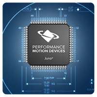 The MC73112, MC73112N, MC71112, and MC71112N ICs from PMD provide torque control of 3-phase Brushless DC and DC Brush motors with advanced features such as FOC (Field Oriented Control), shunt regulation, PWM (Pulse Width Modulation) signal generation with shoot-through protection, overcurrent & overtemperature protection, braking, and more.
These ICs are ideal for a wide variety of applications including spindle control, centrifuges, peristaltic pumps, web tensioning, scanner control, industrial fans & pumps, and more. These ICs are available in two package sizes; a 64-pin TQFP measuring 12x12 mm and a 56-pin VQFN package measuring 7 mm x 7mm. All Juno Torque Control ICs are available immediately and are priced from $12 depending on motor type and quantity.
Available Configurations
Juno torque control ICs are single-axis devices for torque mode control of three-phase Brushless DC motors and DC Brush motors. In addition, two package versions are available as shown in the table below:
|
Part Number
|
Motor Type
|
Package
|
Dimensions
|
|
Brushless DC
|
64-pin TQFP
|
12 x 12 mm
|
|
|
Brushless DC
|
56-pin VQFN
|
7 x 7 mm
|
|
|
DC Brush
|
64-pin TQFP
|
12 x 12 mm
|
|
|
DC Brush
|
56-pin VQFN
|
7 x 7 mm
|
Typical Applications
Torque Control of Brushless DC and DC Brush Motors Using
Analog Command
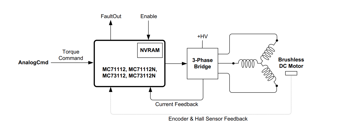
Applications: General purpose amplifier, spindle control, centrifuge control, drug infusion, precision liquid pumping,
turbine control.
In this configuration the MC71112, MC71112N, MC73112, or MC73112N IC receives direct analog commands
representing the instantaneous desired torque. For Brushless DC motors Hall sensors normally provide
commutation feedback. If encoder signals are available however Halls are not required as long as the motor can
move freely during startup (using an algorithmic phase initialization procedure). For DC Brush motors neither Hall
sensor or encoder signals are used for torque control.
In the diagram above a Brushless DC motor is shown but similar torque control can be provided for DC Brush
motors.
Torque Control of Brushless DC and DC Brush Motors Using SPI
Command
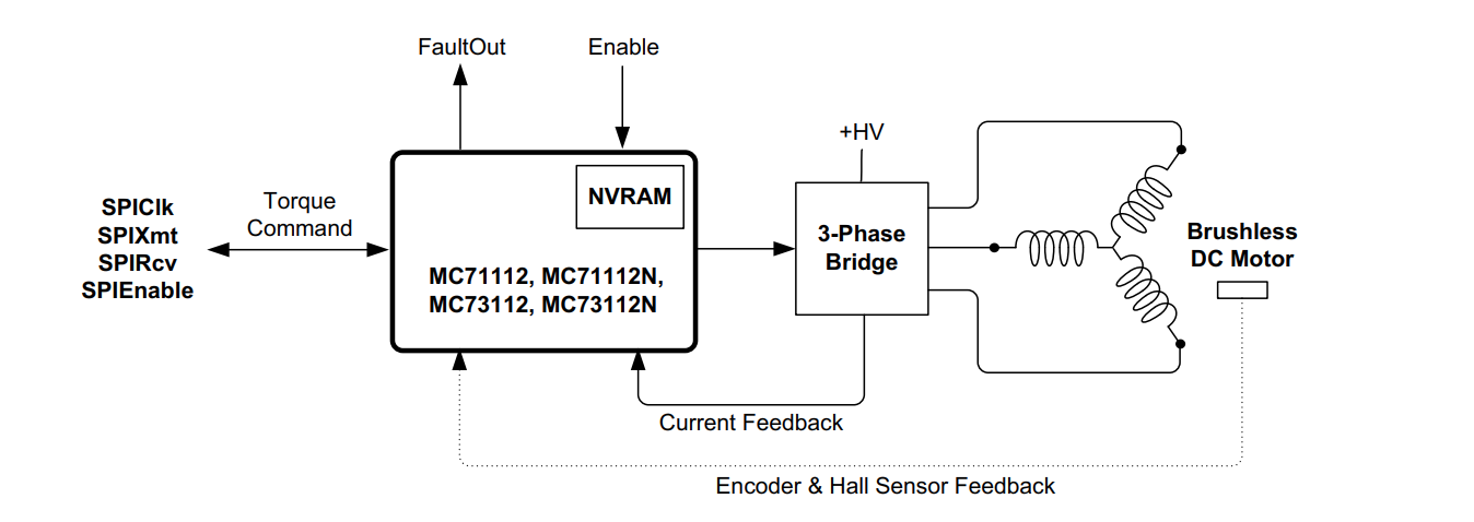
Applications: General purpose amplifier, spindle control, centrifuge control, drug infusion, precision liquid pumping,
turbine control.
In this configuration the MC71112, MC71112N, MC73112, or MC73112N IC receives 16-bit digital SPI (Serial
Peripheral Interface) commands representing the instantaneous desired torque. For Brushless DC motors Hall
sensors normally provide commutation feedback. If encoder signals are available however Halls are not required as
long as the motor can move freely during startup (using an algorithmic phase initialization procedure). For DC Brush
motors neither Hall signals nor encoder signals are used.
The above diagram shows a Brushless DC motor but similar torque control can be provided for DC Brush motors.
Torque Control of Brushless DC and DC Brush Motors Using
Serial Host Command
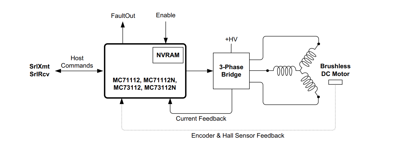
Applications: Microprocessor controlled servo motor drive, programming of MC7x112 IC NVRAM.
In this configuration a microprocessor or PC communicates via the MC7x112’s serial host command port to control
the motor torque. For Brushless DC motors Hall sensors normally provide commutation feedback. If encoder signals
are available however Halls are not required as long as the motor can move freely during startup (using an
algorithmic phase initialization procedure). For DC Brush motors neither Hall signals nor encoder signals are used.
Another use of this configuration is during set up to store the production configuration of the MC7x112 IC into its
NVRAM.
Torque Control Of Servo Motors with PMD Magellan Motion
Control IC
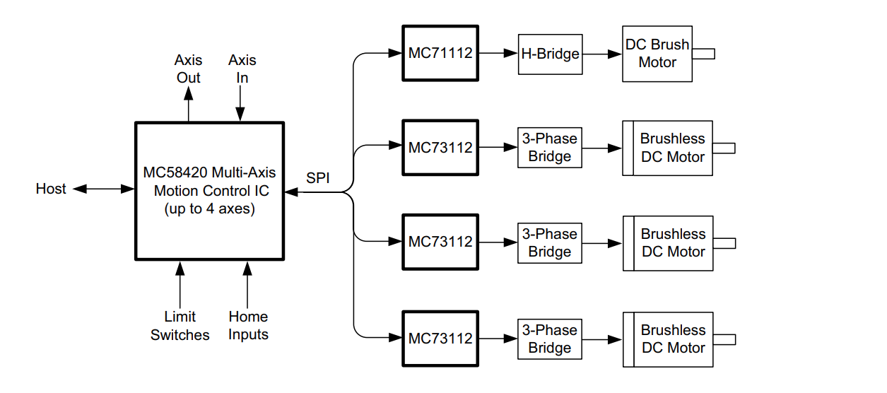
Applications: General purpose multi-axis motion control, laboratory automation, scientific instruments, XY stages,
multi-dimensional contouring, semiconductor equipment.
PMD’s MC5x000 Magellan Motion Control ICs provide up to four axes of profile generation, position servo loop
control, pulse & direction signal generation, and numerous other synchronization and control features. In this
application one or more MC7x112 ICs (one per motor axis) connect to the Magellan IC via SPI and provide high
performance current control and motor amplifier management for Brushless DC or DC Brush motors.
For more information on MC5x000 positioning control ICs refer to the Magellan Motion Control IC User Guide.
Functional Overview
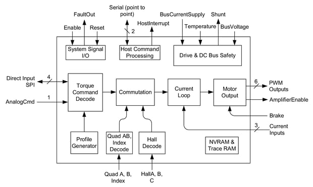
Figure 1: Internal Block Diagram
At power-up or reset, the MC7x112 ICs check for the presence of stored configuration commands in their NVRAM. If NVRAM is programmed, the stored configuration commands are read into the chip, providing parameter information that will be used during operation. If no initial configuration is stored in NVRAM, then default values are used and information will then be sent by serial from a host device such as a microprocessor.
Depending on how the control loop has been configured an external analog signal may serve as the torque command value, or an SPI (Serial Peripheral Interface) data stream may be used for this command value.
Current control is performed via direct input of analog signals representing the instantaneous current through the motor coils. These signals are typically derived from external dropping resistors or Hall sensors at the amplifier circuitry. This analog current information is then combined with the desired current for each phase to generate PWM signals.
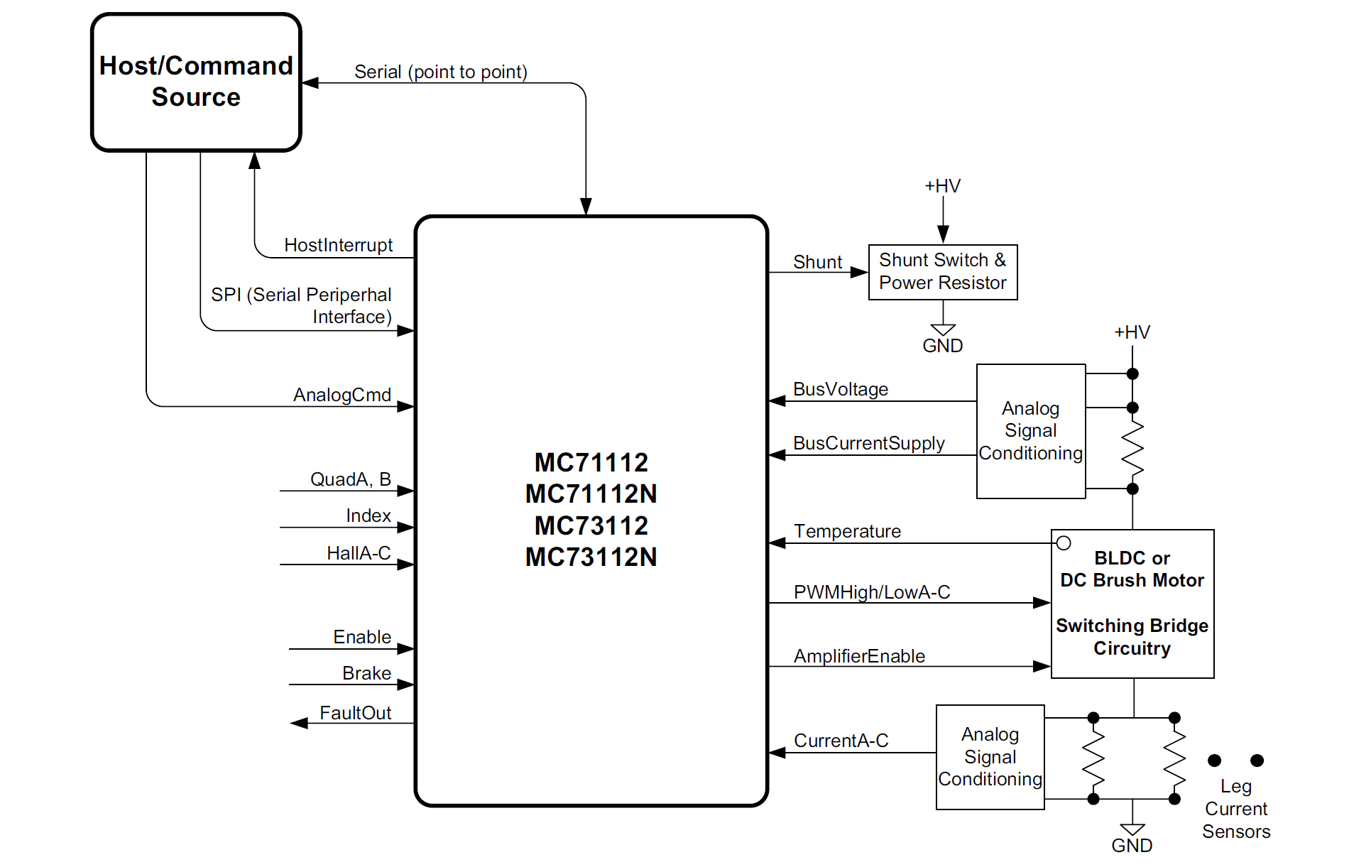
Figure 2: Signal Connections Overview
To create a complete torque controller MC7x112 ICs are connected to switching amplifiers, typically MOSFET or IGBT-based. A programmable dead time function and other timing control parameters ensure that switch synchronization is optimal over the entire operating range of the driven motor.
A number of safety features are incorporated including shunt control, I2t current limiting, brake signal input, DC bus overvoltage and undervoltage detect, overcurrent detect, and overtemperature detect.
Key Features
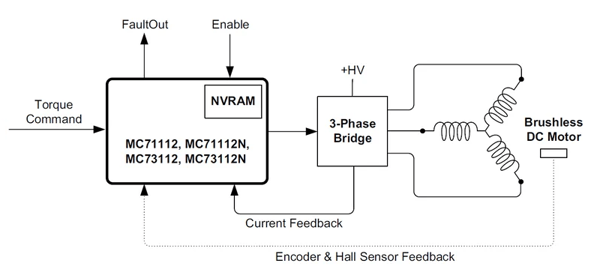
Figure 3: System Control Flow Diagram
Field Oriented Control (FOC) of BLDC motors- Field Oriented Control is an advanced commutation and current control technique that allows BLDC motors to run more efficiently, with a higher power factor, with smoother motion (less torque ripple), and with no compromise in dynamic response to speed changes. The MC73112 and MC73112N BLDC torque control ICs provide FOC both with Hall only commutation and with encoder-based commutation. Additional control modes include third leg floating and voltage mode operation.
Typical control applications include high speed spindles, centrifuges, electric vehicles, pumps, turbines, automated catheters, pick & place machines, semiconductor equipment.
Precision torque control of DC Brush motors - The MC71112 and MC71112N ICs provide precision torque control for DC Brush motors and single phase voice coil and solenoid type actuators. Utilizing internal A/Ds and external dropping resistors or Hall effect sensors, current control resolutions of 1 part in 10,000 are possible. The torque output is updated with a frequency of 40 kHZ. In combination these two features allow extremely precise torque control of the motor or actuator, very rapid torque command changes, or both.
Typical control applications include DC Brush Motor control, precision force generation, actuators, voice coils, solenoids control, surgical actuators, haptics, and precision force measurement.
PWM (Pulse Width Modulation) signal generation. Both the BLDC and DC Brush versions of the MC7x112 Torque Control ICs provide individual high/low switch output for control of digital MOSFET or IGBT switching amplifiers. The available PWM frequency range is 20 kHz to 120 kHZ, with programmable shoot through protection, current read time, and an integrated brake control signal for safety shutdown of motor in one of two programmable modes. A Shunt PWM output is provided for reducing excess DC Bus voltage or in conjunction with battery regen circuitry.
Typical control applications include digital switching amplifier control, safety braking, shunt regulation control, MOSFET motor amplifiers, IGBT motor amplifiers.
Field Oriented Control & Current Loop
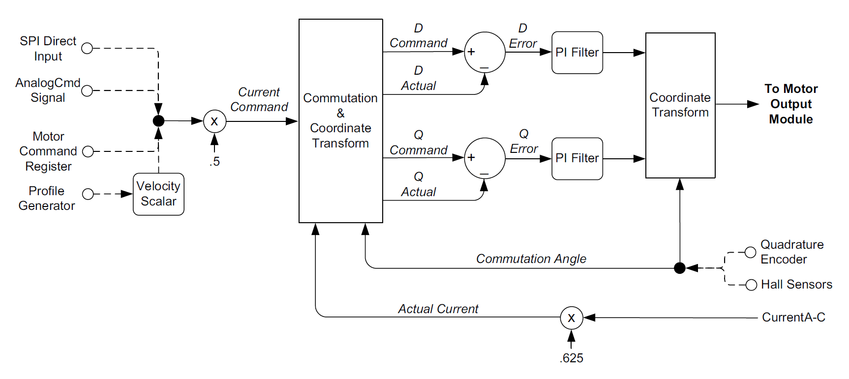 Figure 4: Current Loop & Commutation Control Flow
The figure above provides a summary of the control flow of the MC7x112's current loop & commutation module. Current control is a technique used for DC Brush and Brushless DC motors for controlling the current (and therefore the torque) through each winding of the motor. By controlling the current, response times improve, motor efficiency is higher, and motion smoothness increases. Commutation is used with Brushless DC motors only and utilizes information about the motor’s rotor angle to drive the multiphase motor output.
The digital current loop utilizes the desired current for each motor winding along with the actual measured current which is input by direct analog signal input into the IC. For Brushless DC motors these signals are then algorithmically converted from a non-rotating coordinate frame to a rotating frame. The converted result is referred to as the D phase current and the Q phase current. The commanded and actual D and Q phase currents are then subtracted, and an error generated, which in turn is passed through a PI (proportional, integral) filter.
Finally, the output of the D and Q phase PI filters are converted back into the 3-phase non-rotating reference frame and output as motor commands for each phase of the motor. This commutation and current control technique is known as Field Oriented Control (FOC), and requires information about the motor rotor’s phase angle to generate correctly phase output signals. The large majority of applications will use FOC for Brushless DC motor control. FOC usually provides the highest top speeds and more energy efficient operation of the motor.
A second option for Brushless DC motors is available for the Juno ICs however known as third leg floating. Third leg floating can sometimes provide a higher top speed than FOC. It uses a different method than FOC in that only two of three legs are driven at any instant with the third, non-driven leg, left floating. Third leg floating control mode may be considered with Hall-commutated Brushless DC motors.
The choice of field-oriented control or third leg floating is user programmable. For DC Brush motors the current loop method is fixed and does not need to be set by the user. In addition, because they are single phase devices, the current loop does not require information about the motor’s rotor angle.
Settable Parameters
All of the required specialized algorithms, tables, and calculations are contained inside the IC. The user needs to simply set the control parameters for their specific motor & application so that the resultant torque control and motion is optimum.
To control the current loop in FOC mode three parameters are specified for both the D loop and the Q loop; Kp, Ki, and I limit. Two of these are gain factors for the PI (proportional, integral) controller, one is a limit for the integral contribution.
Determining correct Kp, Ki, and I limit parameters for the current loop controller gains can be done in a number of ways but the easiest is to utilize the auto-tuning facility provided within PMD’s Pro-Motion software package. If a DC Brush motor is used or if the current loop is set to third leg floating then only the Q loop Kp, Ki, and Ilimit parameters are set.
PWM (Pulse Width Modulation) Signal Generation
The MC7x112 torque control ICs can control high-efficiency MOSFET or IGBT power stages with individual high/low switch input control. DC Brush motors are driven in an H-Bridge configuration consisting of 4 switches, while Brushless DC motors are driven in a triple half-bridge configuration consisting of 6 switches.
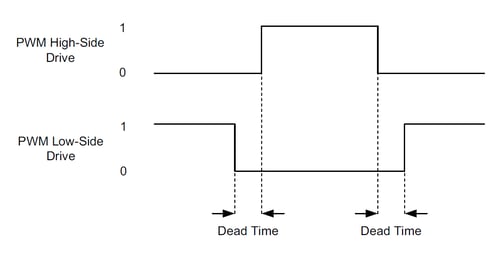 Figure 5: PWM High/Low Signal Generation
In PWM High/Low mode two output pins are used per motor or per motor phase, allowing separate high-side/lowside control of each bridge switch. In this scheme, as the figure above shows, the high side output and the low side output are never active at the same time, and there is generally a period of time when neither output is active. This period of time is called the dead time and provides a shoot through protection function for MOSFET or IGBT switches.
The dead time is specified in nSecs. The correct value can be determined from the MOSFET or IGBT IC manufacturer’s data sheet.
In addition to dead time, some high side switch drive circuitry requires a minimum amount of off time to allow the charge pump circuitry to refresh. This parameter is known as the refresh time and has units of nSecs. The related parameter of refresh time period, which is the time interval between off time refreshes has units of current loop cycles.
It is also possible to control the maximum allowed PWM duty cycle. This may be useful to limit the effective voltage presented to the motor windings, or to provide some other needed off-time for the switching amplifier circuitry.
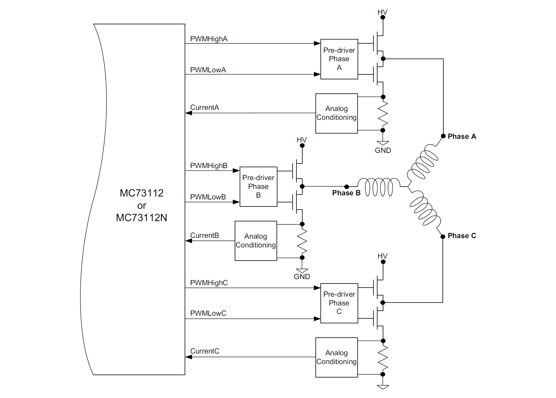
Figure 6: Brushless DC Motor Bridge Configuration
Settable Parameters
As was the case for FOC control, MC7x112 ICs come 100% ready for PWM signal generation. The user needs to simply set the PWM configuration parameters for their specific application. To control PWM generation five parameters are specified; the PWM switching frequency which may be set to 20, 40, 80, or 120 kHz, the PWM dead time which is specified in nSecs, the PWM refresh time and the PWM refresh period, which together control charge pump circuitry refresh timing, and the PWM duty cycle limit.
Appendix I MC7x112 IC Developer Kits
All of the 64-pin TQFP package MC7x112 ICs are supported via the DK78113 developer kit board. The DK part numbers differ in the specific type of IC that is installed.
|
Developer Kit
Part Number |
Juno IC
Installed |
Motor
Supported |
Comments |
|
MC71112
|
DC Brush
|
Torque control
|
|
|
MC73112
|
Brushless DC
|
Torque control
|
The 56-pin VQFN IC package MC7x112N torque control ICs are supported by the DK73112N developer kit board. The DK part numbers differ in the specific type of IC that is installed.
|
Developer Kit
Part Number |
Juno IC
Installed |
Motor
Supported |
Comments |
|
MC71112N
|
DC Brush
|
Torque control
|
|
|
MC73112N
|
Brushless DC
|
Torque control
|
Each developer kit includes:
- Standalone board with easy to access connectors for fast setup and testing
- Pro-Motion auto tuning and axis wizard setup software
- Complete Juno manuals or PDFs
- Extensive application schematic examples
Appendix II Juno Torque Control IC Specifications
Configurations, Parameters, and Performance
|
Control command sources
|
AnalogCmd
|
Torque command is provided via external direct analog input
|
|
|
SPI
|
Torque command is provided via external SPI (Serial Peripheral Interface) direct input
|
|
|
Internal profile
|
Torque command is provided via internal profile generator function
|
|
|
Motor Command Register
|
Torque command is provided via host command to a 16-bit register.
|
|
Host communication modes
|
Point to point asynchronous serial
|
|
|
Serial port baud rate range
|
1,200 baud to 460,800 baud (1,200, 2,400, 9,600, 19,200, 57,600, 115,200, 230,400, 460,800)
|
|
|
Motor output modes
|
PWM High/Low
|
Individual high and low drive signals for each bridge switch
|
|
|
Sign/Magnitude PWM
|
Sign and magnitude drive signals for an H-bridge
|
|
Commutation rate
|
39.06 kHz
|
|
|
Current loop rate
|
19.53 kHz
|
|
|
Current measurement resolution
|
12 bits
|
|
|
PWM resolution & rates
|
1:1,536 @ 20 kHz
1:768 @ 40 kHz
1:384 @ 80 kHz
1:256 @ 120 kHz
|
|
|
DC Bus & safety signals
|
Brake, BusVoltage, BusCurrentSupply, Temperature, Shunt
|
|
|
Amplifier output signals
|
AmplifierEnable, PWMHighA, PWMLowA, PWMHighB, PWMLowB, PWMHighC, PWMLowC
|
|
|
Serial communication signals
|
SrlXmt, SrlRcv
|
|
|
Analog command signals
|
AnalogCmd
|
|
|
SPI command signals
|
SPIXmt, SPIRcv, SPIClk, SPIEnable
|
|
|
SPI frequency range
|
1.0 MHz - 10.0 MHz
|
|
|
Encoder input signals
|
QuadA, QuadB, Index
|
|
|
Position range
|
-2,147,483,648 to +2,147,483,647 counts
|
|
|
Hall sensor signals
|
Hall A-C
|
|
|
Miscellaneous control signals
|
Enable, FaultOut, HostInterrupt, Reset
|
|
|
Drive safety functions
|
Over current detect, over temperature detect, over voltage detect, under voltage detect, I2t current foldback
|
|
|
Brake input modes
|
Passive braking, full disable
|
|
|
Output limiting
|
I2t, current, and voltage limit
|
|
|
Maximum encoder rate
|
40 Mcounts/sec
|
|
|
Cycle time range
|
102.4 microseconds to 1.114 seconds
|
|
|
Position-capture triggers
|
Index signal
|
|
|
Internal RAM
|
6,144 16-bit words
|
|
|
Maximum number of simultaneous trace variables
|
4
|
|
|
NVRAM storage size
|
1,024 16-bit words
|
|
Appendix III Physical Dimensions
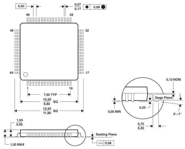
Physical Dimensions, 64-pin TQFP Package
All dimensions are in millimeters.
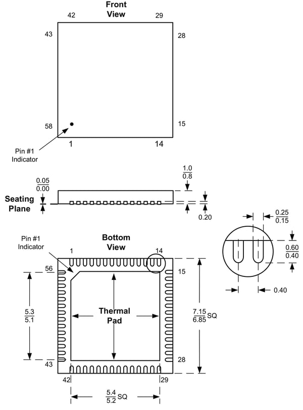
Notes:
- Juno IC is RoHS compliant and free of Bromine and Antimony based flame retardants.
- Moisture sensitive level: MSL 3
Physical Dimensions, 56-PIN VQFN Package
Notes:
- Juno IC is RoHS compliant and free of Bromine and Antimony based flame retardants.
- Moisture sensitive level: MSL 3
Additional Resources
- MC7X112 Torque Control IC Datasheet
- Juno Developer Kits
- Field Oriented Control (FOC) - A Deep Dive (Article)