Instead of wasting the potential energy associated with the BackEMF voltage of a vehicle's electric motor via heat loss, it can be used to recharge the vehicle's battery and therefore recover energy.
The Regenerative Braking Deep Dive: Part I introduced the topic of regenerative braking. This included the conditions under which regenerative braking can occur and the electrical properties that allow it to take place. The discussion will be continued by creating a theoretical model to prove the existence of steady-state regeneration as well as gain insight into estimating the energy recovered during regenerative conditions. Once again, an electric vehicle will be selected for investigation due to its intrinsic potential for steady state regeneration.
In this article, a mechanical and theoretical model of an electric vehicle will be constructed. The model will be simplified by adhering to rigid body analysis only. This implies that elastic deformation of components like axles and drive shafts will be ignored and assumed to be zero. Additionally, there will be no frictional components included in the model which implies the wheel and motor bearings are ideal and the gearing mechanism has no efficiency loss. This also implies that there is no wind drag on the model. This model can be used to gain insight into the nature of the energy recovery, however, if a real-world numerical estimate of the amount of energy recovered is required, the frictional and efficiency components need to be accounted for properly in the modeling process.
Mechanical Model
The analysis will be continued by creating a mechanical model of the electric vehicle. The model will be simplified by adhering to rigid body analysis only. This implies that elastic deformation of components like axles and drive shafts will be ignored and assumed to be zero. Additionally, there will be no frictional components included in the model, which implies the wheel and motor bearings are ideal and the gearing mechanism has no efficiency loss. This also implies that there is no wind drag on the model. This model can be used to gain insight into the nature of the energy recovery; however, if a real-world numerical estimate of the amount of energy recovered is required, the frictional and efficiency components need to be accounted for properly in the modeling process.
The model of the electric vehicle will be defined by a set of mechanical and electrical parameters. Figure 1 defines two of these: the mass of the vehicle and the slope of the hill.
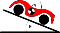
Figure 1: Vehicle on a slope
To model the motion of the vehicle and the resulting energy recovery, the mechanical drive train of the vehicle must be analyzed. This includes the motor and a gear assembly attached to one wheel. The other three wheels are free to spin. Figure 2 depicts the forces and torques acting on the drive train of the vehicle.
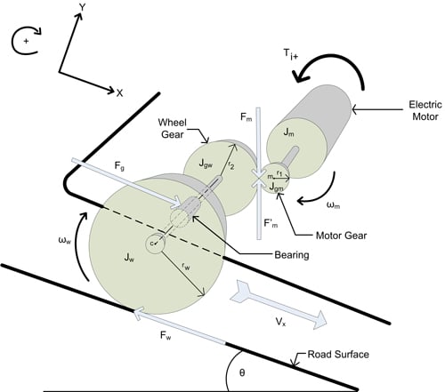
Figure 2: Drive train model
All translational motion of the vehicle occurs along the X-axis which is always parallel to the road surface. The motor and motor gear rotate together as one rigid body. The “Ti+” arrow indicates the direction of torque produced by a positive current. In accordance with the rotation direction defined here, this will be torque in the negative direction. F’m is the force of the wheel gear acting on the motor gear. Summing the torques about the center of the motor gear (m) results in:

Substituting Kti for Ti+ and solving for F’m results in:

The wheel gear and wheel are also treated as one rigid body where the rotation of the wheel gear is equal to the rotation of the wheel. The axle bearing (see Figure 2) acts on this rigid body and ultimately transfers all gravitation and translational inertial forces. Summing the forces acting on this rigid body along the X axis results in:

Summing the torques about the center of the wheel (c) results in:

Solving for Fw:

A few system observations will allow for some useful substitutions.
Making substitutions in the force equation and letting  :
:


The rotational velocity terms will now be replaced with linear velocity terms:

And then solve for:

Expansion of the motor model
To facilitate use of the electrical equation in a system analysis, the BackEMF voltage will be expressed as a function of the vehicle velocity:

Substituting back into the motor equation and solving for di/dt:

Electromechanical model
At this point two first order ODEs have been created, one derived from mechanical properties and the other derived from electrical properties. These can be combined to create a system of 1st order non-homogenous ODEs:
X=AX + B
Where

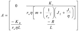
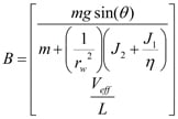
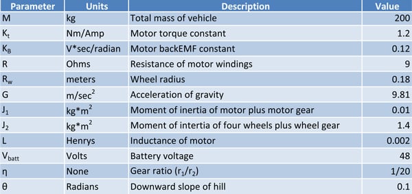
This becomes the foundation for a mathematical model of the vehicle whose solution will provide an expression for the current as a function of time. The contents of matrix A and B are constants and therefore a solution for the ODEs exists. Since the goal is to gain insight into quantifying the energy recover, appropriate numerical values will be established for the various model parameters.
The scaling of the numerical parameters are based on a golf cart as opposed to a typical passenger vehicle. At this point, MATLAB® will be used to solve the ODEs and provide numerical data that can be used to calculate power flow under specific conditions.
TABLE: Parameters, units, descriptions, values for electric vehicle regeneration model
Part 1 of this article made the claim that regeneration can exist as a steady state condition. The model will now be set up to run under those conditions. The initial state of the vehicle is sitting on the downward slope of a hill with the parking brake engaged. The motor drive stage is disabled such that all MOSFETSs are open (not conducting). This means there is no potential for current flow in the motor since there is no path for that current to flow along. The parking brake is now disengaged (t0=0) and the vehicle begins to accelerate down the hill. The motor also begins to rotate and generate BackEMF voltage, however, this does not produce any current since the MOSFETs are still open. There is no braking of any kind occurring in this state.
After 8 seconds (t1=8) the vehicle has accelerated up to about 14 mph (see Figure 4), at which point the drive stage is enabled and running with a constant duty cycle of 25%. The BackEMF voltage of the motor will now produce current since a path exists for the current to flow in. Also, note that the BackEMF voltage is larger than the effective voltage which means the current will grow negative. It reaches a value of –8Amps almost immediately (within 8ms) (t1+). However this current will cause the motor to produce a braking torque which slows down the vehicle thus reducing the BackEMF voltage. The force of gravity will keep the absolute BackEMF voltage above the effective voltage (which has opposite polarity). This will permit a steady state condition to exist where velocity is positive, current is negative and the effective voltage is positive (tss).
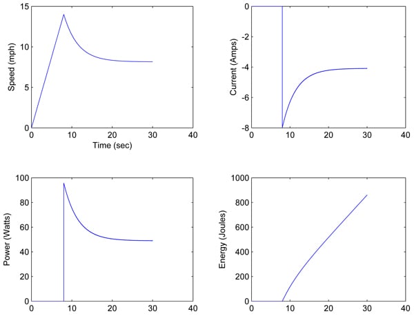
Figure 4: State Variables and Energy Profile
Figure 5 shows the various states that have transpired while running this model. Beginning with t0 and ending with tss. Regeneration begins as soon as the drive stage (MOSFETs) is enabled which allows the BackEMF voltage to produce current. After about 10 seconds the speed and current are almost at a steady state. The model is now in a steady state region of regenerative braking.
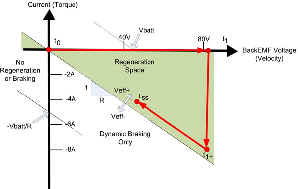
Figure 5: Regeneration Space
Part 1 of this deep dive derived a proof that the average power flow into the battery can be defined by the battery voltage times the current times the duty cycle percentage.
P = Vbatt * I * DutyCycle
The steady state current is about -4 amps and subsequently the power flow is about 48W. However, the typical efficiency of a lead acid battery is 75-85%. This means that only a percentage of the energy flowing into the battery will be stored as electrical energy that can be later used. The remainder of the power is lost due to thermal heating. In this case, the rate of energy being stored that can later be used is about 35 - 40 W. Further limitations arise as a result of battery properties. One of which being that the recharge efficiency will reach zero when fully charged.
To The Laboratory!
This deep dive (Parts 1 and 2) has presented the theory and accompanying numerical model to prove that gravitational energy can be converted into electrical energy and then stored. A simple experiment was performed whereby a gravitation load causes a Brushed DC motor to spin thus creating a BackEMF voltage potential across the motor windings. A green LED is placed across the motor leads which are exposed to the BackEMF voltage. Figure 6 illustrates this setup.
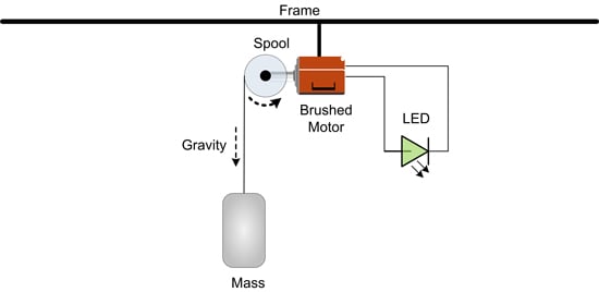
Figure 6: Experiment Setup
As demonstrated by the video above, the BackEMF voltage is large enough to induce current flow in the LED which causes it to glow a green color. As the motor speed increases the current in the LED does as well. The increase in current causes the LED color to change from green to amber and then briefly to red. At the end of the video the motor slows to a halt because the gravitation load had been removed. Since the motor is not moving the LED does not see any voltage potential and the current flow is gone.
In case you skipped ahead, here's Part 1 - Regeneration Braking: Steady State Analysis
Written by:
Thomas Keller
Senior Applications Engineer
Performance Motion Devices, Inc.
You may also be interested in:
- Digital Current Loop Significantly Quiets Step Motor Noise
- Optimizing A Control Architecture for High Accuracy Syringe Dispensing
- Get the most out of your motion controller using Torque FeedForward
- Selecting The Right Motion Control Amplifier
Stay ahead of the competition.
If your existing equipment needs a performance boost or if you need to develop a new product in the shortest development time possible, learn about motion control solutions from Performance Motion Devices.


