Many motion applications require high accuracy both during and at the end of the move. Even if you are using perfectly optimized PID (proportional, integral, derivative) values to control position, the compensation loop is never perfect because it must manage the influence of a wide range of system forces. Feedforward is an ideal way to deliver motion accuracy.
Can we improve performance by adding motion control elements outside of the PID loop? The answer is yes, and in this deep dive we will look at torque control and the related subject of torque feedforward, which can make your system run smoother, and deliver better accuracy.
I’m such a torque
Figure 1 (below) shows a typical overall electronic motor control scheme, with a profile generator, a PID position compensator, and a current loop. Current flowing through the motor is ultimately what generates torque.
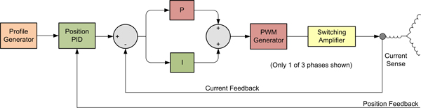
Figure 1: Typical electronic motor control scheme
Some simpler control systems dispense with the current loop and directly output a voltage command to the motor, which in turn creates current in the motor coils. As it turns out though, the relationship between the voltage at the motor’s coils and the actual current flowing through the motor can be rather complicated.
For the majority of motion control applications, a current loop will be used, which measures and actively attempts to control the motor current. Modern controllers perform this task digitally, using sensors, A/Ds (Analog to Digital converters), and one of several current sensing schemes - depending on the target cost and performance of the drive. More accurate schemes continuously measure or infer the current control through each leg, while simpler schemes measure one current for the whole motor.
Watching the wheels go round
OK, so now we’re finally spinning our wheels. We set up our position PID loop and start the machine moving. Immediately though, despite a lot of fine-tuning of PID parameters, we find that we can not perfectly track the desired profile. There always seems to be a lag, or overshoot, particularly while the machine is in motion.
Why is this? One reason is that for a PID loop to output anything, it must have an error to operate on. So, by definition, the motion will have position error. Another reason is that real-world systems must balance the desire for high accuracy with the need for stable, non-oscillating motion operating over all profiles, and all loads. PID gains ultimately represent a compromise between these two goals.
If there were some way of giving the motion controller more information about the machine, perhaps we could ease the burden of the PID loop, and reduce position errors.
It turns out that there is, and this brings us to the main topic of this deep dive. For the next several sections, we will discuss various methods of adding a torque command directly to the PID output to help reduce the burden on the PID loop. Our goal is to compensate for machine or motor forces that we know about in advance, thereby reducing the torque command output needed from the PID.
I’ve fallen and I can’t zero my servo error
The simplest possible kind of torque feedforward in motion is a constant bias in the desired torque command. The classic configuration that benefits from this is a vertical axis that is influenced by gravity. The optimal output bias for this application would generate a torque just large enough to lift up the axis so that the PID loop, at least in theory, doesn’t have to do anything to compensate for the force of gravity.
In the practical world, several factors don’t allow perfect compensation. To begin with, load masses are often variable. In addition, motors and mechanisms do not behave exactly the same, even if built to tight tolerances. So, in adding a torque compensation value, our expectation should be to lower, but not eliminate, the amount of work that the PID loop has to do.
In addition to a constant bias value, what additional terms can help zero-out forces experienced by the machine? Enter two popular feedforward approaches: velocity-proportional feedforward, and acceleration-proportional feedforward.
Figure 2 shows an axis moving through a trapezoidal move profile, and a possible resultant position error response from an actual machine axis.
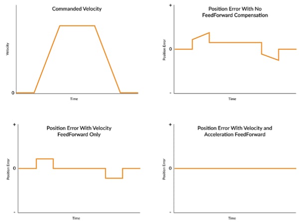
Figure 2: Move through a trapezoidal move profile
Any force that is induced by the movement and can be determined in advance by the machine controller is a candidate for feedforward compensation. In the case of velocity feedforward, there are various kinds of frictional forces that may counteract the machine’s motion in a way that is proportional to the velocity of the axis. If we can determine the magnitude of these forces, we can compensate.
Exactly the same applies to acceleration-proportional forces, beginning with the tendency of the machine’s load to resist being moved. If the mass of the machine load is known, then we should be able to feedforward an acceleration-proportional torque that pre-compensates for the force generated by the inertia of the load, also called the reflected torque, during acceleration and deceleration.
The figure above shows the position error with no feedforward compensation, velocity feedforward applied, and both velocity and acceleration feedforward applied. As it turns out, there is no need to explicitly measure these on-the-fly machine forces. The PID loop, in its efforts to keep up with the commanded profile, shows us the torque output needed to compensate. If you try this yourself, this technique is made simpler by zeroing the I term, and using just P and some D term.
Looking at the shape of the servo lag allows you to determine if your machine is experiencing velocity-proportional lags, acceleration-proportional lags, or both. As before, because loads may change and machines vary, we hope to lower the servo lag, but don’t expect it to be zero.
You may also be interested in Servo Motor Tuning – Rocket Science or Walk In the Park?
Motion kinematics
Machines that are built with ‘orthogonal’ actuators, such as an X Y stage, have simple reflected forces that are relatively easy to compensate for.
Some robot configurations, however, such as PUMA-style articulated arms (these are the robots you see welding cars in factories) have much more complicated reflected torques, and include entirely new forces such as centripetal forces. Also, for these robots, as arms rotate, previously constant reflected forces such as gravity may change. Figure 3 provides a simple diagram that illustrates this point. The reflected gravity-compensating torque required for the motor at Position 1 is quite different than at position 2.
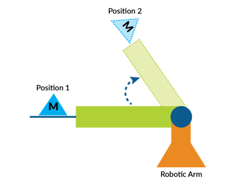
Figure 3: PUMA-style articulated robot arm
In theory, with enough information about the robot, the load, and the motion profile, these forces can be compensated for, and in the rarified atmosphere of high end articulated arms, such kinematic transformations and torque compensation techniques are common.
Even fancier techniques may be applied such as building a ‘observer’ that looks at performance dynamically to infer what the load is, or how friction changes from machine components that are aging over time. While useful in specific industries, such exotic techniques are generally not provided by general purpose off-the-shelf motion controllers.
You may also be interested in Motion Kinematics
A bump in the road
Another major category of forces that we can compensate for electronically comes from the motor itself. The reason for this is that motors, whether rotary or linear, do not provide perfect conversion of current flow into generated torque. There are several sources of torque output ‘bumpiness’, and this bumpiness gets injected into the machine mechanisms, making the job of the PID compensator more difficult.
One such effect is detents. Detents are easily felt in a step motor as regular bumps during rotation. With Brushless DC motors, these bumps are fewer per rotation, but just as undesirable.
By mapping the torque profile of a motor through one complete electrical cycle, it is possible to develop compensating motor commands (yet another form of feedforward) that can counteract detents. By way of example, Figure 4 graphs a detent-compensating table that was constructed for a motor from the PMD lab, which we will feature in a video experiment below.
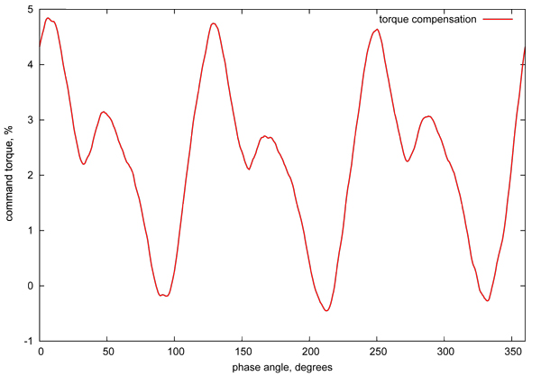
Figure 4: Torque compensation graph
It is worth noting that step motors can have their positioning accuracy improved by a similar technique. At a fine resolution, even when presented with a perfect sinusoidal waveform, step motors do not move in exact increments. Small adjustments to the microstepping drive Sin/Cos lookup table can improve microstepping accuracy.
If all of this sounds like a lot of effort, in the case of brushless DC motors, choosing a ‘slotless’ motor, so called because it eliminates slotted iron laminations in the stator, is a good option, and will virtually eliminate detents. With step motors, there are ‘skewed rotor’ techniques which minimize, but do not eliminate detents. Both of these motor types tend to cost more, but may often be the best choice.
On the other hand, once the motion controller moves to a software-based platform such as a DSP (Digital Signal Processor) these motion techniques do not add cost. So in circumstances where motor cost is an issue, or just to take performance to the next level, you should consider electronic compensation.
Go ahead, make my output more linear
To close the discussion of torque compensation, we come to techniques that attempt to linearize the torque output of a motor.
As it turns out, as a motor rotates, it does not output exactly the same torque, even when presented with a constant current. Torque output, depending on the motor, can vary +/- 20% within one full electrical revolution or more.
Fully correcting this for all operating conditions, all torque values, and all rotation positions are complicated. But for delicate applications, a small torque-proportional compensation term for various phase angles of the motor can improve motor linearity significantly, and therefore reduce torque ripple injected into the mechanism.
To the motion control laboratory!
To set up this months video experiment, we rummaged through our pile of brushless DC motors and found one that had modest, but measurable detents. Could an electronic compensation technique such as described above improve the performance of a low-cost rotary Brushless motor? Yes!
An ION Digital Drive from Performance Motion Devices, loaded with a torque compensation table (shown in Figure 4), controls the motor. As the motor rotates, for each output position of the commutator, the motor torque command in this table is directly added to the output of the PID position controller, thereby counteracting the torque ripple from the motor detents.
It is actually much easier to feel torque output than it is to visualize it. As we put this experiment together, it was rather uncanny to twist the motor and feel the motor’s detents magically ‘disappear’ when the compensator was switched on!
In any case, to visualize the effect, we connected the shaft of the motor to a pulley, and wound wire around the pulley and ran it into to a sensitive hand-made ‘scale’, consisting of a rubber band with an indicator glued to it. As the motor spooled out, the thin elastic stretched by an amount proportional to the force required to move the motor, which was determined by the torque output of the motor at that position.
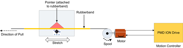
Figure 5: Illustration of setup used in videos below
Video 1: Move without compensation
Video 2: Move with compensation/strong>
As the video shows, the uncompensated motor torque output is noticeably bumpier, while the same motor compensated system is smoother.
PMD Motion Control Solutions That Provides Feedforward
Since 1992, Performance Motion Devices has been producing motion control solutions, including ICs, modules, and boards, that provide advanced motion control of servo motors. Millions of our ICs are embedded into high-performance motion control solutions. While different in packaging, all PMD products are controlled by C-Motion, our easy to use motion control language, and are ideal for use in healthcare, such as medical analytical instruments and operating room equipment, semiconductor, robotic, and industrial motion control applications.
ION/CME N-Series Digital Drives
N-Series ION Digital Drives combine a single axis Magellan IC and a high performance digital amplifier into an ultra-compact PCB-mountable package. In addition to advanced servo and step motor control, N-Series IONs provide S-curve point to point profiling, field oriented control, downloadable user code, general purpose digital and analog I/O, and much more. With these all-in-one devices building a custom controller board is a snap, requiring you to create just a simple 2 or 4-layer interconnect board.
Learn more >>

Juno Velocity & Torque Control ICs
The Juno family of ICs are perfect for building your own low cost, high performance controller. Juno's excel at velocity and torque control, with features such as FOC (Field Oriented Control), profile generation, high/low switching amplifier control signal generation, leg current sensing, and more. Available in packages as small as 7mm x 7mm and costing $12 in quantity, these ICs are an ideal solution for your next controller design.
Learn more >>
MC58113 Motion Control IC
The MC58113 is part of PMD's popular Magellan Motion Control IC family and provides advanced position control for BLDC, DC Brush, and step motors alike. Standard features include s-curve profiling, programmable breakpoints, two axes of encoder input, FOC (Field Oriented Control), intelligent performance trace, and more. The MC58113 family of ICs are the ideal solution for your next positioning application challenge.
Learn more >>
Related topics:
- Two Approaches To Building A 3-Axis Gantry Controller Board
- Motors and Motion for Medical
- Haptic Feedback in Motion Control
- S-Curve Profiles - A Deep Dive
- Keep Your Step Motor Position with A Closed Loop Motion Control System
- Mathematics of Motion Control Profiles