Chuck Lewin
Founder and CEO
Performance Motion Devices, Inc.
In addition to providing smoother motion, S-curve trajectory profiles are a vital tool for improving point to point transfer speeds by letting you tune the profile to the load. Best of all these performance improvements are equally applicable for servo motors such as brushless motors and DC Brush motors as they are for stepper motors.
Introduction
By smoothing out the edges, S-curve trajectory profiles reduce abrupt acceleration changes and thereby smooth out the motion. But the actual power of S-curves goes far beyond just smoother moves by allowing the profile to be tuned, thereby optimizing point-to-point transfer speeds for a broad class of machines such as gantries, belt-driven systems, XYZ tables, indexers, embroidery equipment, industrial robots, and more.
S-curves trajectory profiles add 'transition' segments to the traditional 3-phase trapezoidal trajectory profile (accelerate, coast, decelerate) resulting in a 7-phase profile. This is shown in Figure 1.

Figure 1: Velocity and Acceleration Versus Time for an S-Curve Trajectory Profile and a Trapezoidal Trajectory Profile
What makes S-curve profiles so powerful is that they inject dramatically less vibrational energy into the connecting mechanisms and the load. This is true whether the drive motor used is a servo motor such as a brushless motor (also called a BLDC motor) or a stepper motor. Just as importantly, compared to trapezoidal profiles, S-curves provide an additional control mechanism for cancelling oscillations in the load by adjusting the ratio of the profile's transition phases to the constant acceleration phases.
Together these two features can have a dramatic impact on the effective transfer time. The effective transfer time is the time from when the load begins moving to when it finally actually settles. For high speed point-to-point moves a tuned S-curve can reduce the effective transfer time by 25 % or more depending on the nature of the mechanism being controlled.
The trajectory profile characteristic that defines change in acceleration is known as "jerk". In a Trapezoidal trajectory profile the jerk is infinite at the phase transitions, while in an S-curve trajectory profile jerk is a constant value, spreading the change over a non-zero time period. For a given load, the higher the jerk, the greater the amount of energy that will show up as unwanted vibrations in the system, and, the broader the frequency spectrum of this vibration inducing energy will be. This is shown in
Figure 2.

Figure 2: Induced Vibration from S-curve Trajectory Profile and Trapezoidal Trajectory Profile
Comparing the amount and type of vibration energy produced by a trapezoidal profile with an S-curve profile, we see that a trapezoidal profile - because of its instantaneous change in acceleration - injects a relatively large amount of vibration energy into the system, and this vibration energy is spread over a wide range of frequencies. The S-curve motion profile injects less vibrational energy into the load and, just as importantly, the range of these vibrations cuts off rapidly at higher frequencies.
Putting S-Curve Profiles to Work
Now that we understand the principles involved, how can an S-curve be 'tuned' to optimize the transfer times of the actual load?
Finding the optimum S-curve form for a given application is a matter of balancing the time spent transitioning from zero acceleration to maximum acceleration (Phases I & III) as a percentage of the time spent at maximum acceleration (Phase II).
On the one hand, if we spend nearly all our time transitioning (Phases I & III) and very little time at maximum acceleration (Phase II), the motion will be extremely smooth but the total time of the move will have increased. This is because, during Phase I, the S-curve profile travels only a short distance, therefore, the greater amount of time spent here will increase the overall transfer time.
On the other hand, if we spend only a small fraction of time in Phases I and III, then the time of the total move will be minimized, however the profile will not be as smooth and may cause unwanted vibration in the load. Happily, there is a caveat because even relatively brief Phase I and III phases can result in dramatic reductions in load-induced oscillations. Don't forget that you are comparing a large jerk value (for the S-curve profile) with an infinite jerk value (trapezoidal profile), so even a little bit of transition tends to be much better than none at all.
In fact, for a given mechanism there is often a 'magic' value for the S-curve phase ratio. While too little transition time can inject too much vibrational energy, surprisingly, too much transition time can have a similar affect. There is often a specific value for jerk which 'sticks the landing' and significantly or entirely reduces settling oscillation at the end of the move. Finding that value is the goal of the S-curve tuning process.
Practically speaking, unless the weight of the load never changes, or unless the weight of the load is exactly known, you will probably tune the S-curve trajectory shape for a point to point transfer of an average load. But even an average-optimized value can make a big difference in effective point to point transfer times.

Gentlemen, start your engines!
A classic example of S-curve motion versus trapezoidal motion can be found driving your car. Imagine holding your foot on the brake pedal of your car as it decelerates to a stop. If you do not move your foot from the pedal, you will decelerate at a more or less constant rate until the car stops. At the moment the car finishes decelerating, it will lurch backwards and oscillate a few times before settling down.
Now, imagine braking the car at a constant rate but gently lifting your foot up from the pedal just before you come to a complete stop. This is something that most of us (the good drivers) do automatically to avoid jostling the passengers. Using this method, the car doesn’t oscillate.
Letting your foot off the brake at the end of the move is analogous to performing an S-curve profile. It creates a transition phase from constant deceleration to zero deceleration. This simple change results in much lower load oscillation.
S-Curve Versus Trapezoidal Trajectories
Are there applications where S-curve profiles have benefits over trapezoidal profiles beyond improvements in point-to-point transfer time? Yes. One clear instance is when the motor controller is transporting humans. In this case abrupt changes in acceleration are highly undesirable because they can cause discomfort or even nausea. Another instance is transporting a liquid or gel where it is important that the liquid not be agitated.
The following table shows some common applications that benefit most from S-curve trajectory profiling:
|
|
|
|
Faster Transfer Time
|
|
|
Smoother Motion
|
|
Real-World Benefits of S-Curve Trajectory Profiles
Figure 3 shows an apparatus setup in Performance Motion Devices' lab to illustrate the difference between the motion of the drive motor and the motion of the attached load and the important concept that to maximize load transfer time performance S-curve trajectory profile tuning is one of the best tools available. The basic elements are a brushless linear motor, a load consisting of an inverted pendulum held by elastics and an encoder that records the movement of the load.
The controller for this setup is an N-Series ION Drive from Performance Motion Devices which is operated as a servo motor controller configured for BLDC motor control.

Figure 3: Experimental Setup to Measure Displacement between BLDC Linear Motor and Compliant Load
The load can rotate freely around the attachment joint and is held in a vertical position by the tension of the elastics. This setup emulates a real-world machine where the load is connected via a mechanical assembly to the drive motor. All mechanical linkages have some 'give', which is represented by the elastics. Although exaggerated and simplified, this setup provides useful results that illustrate some of the basic principles of S-curve trajectory profiles.
The graph below shows data from the encoder collected by the ION brushless motor drive and the following table provides a numerical summary of the results of the experiment. The graphed data shows the displacement (the difference) between the load position and the motor position. In an infinitely stiff system this displacement would always be zero, but in real world systems where the motor drives an attached mechanism that is never the case.
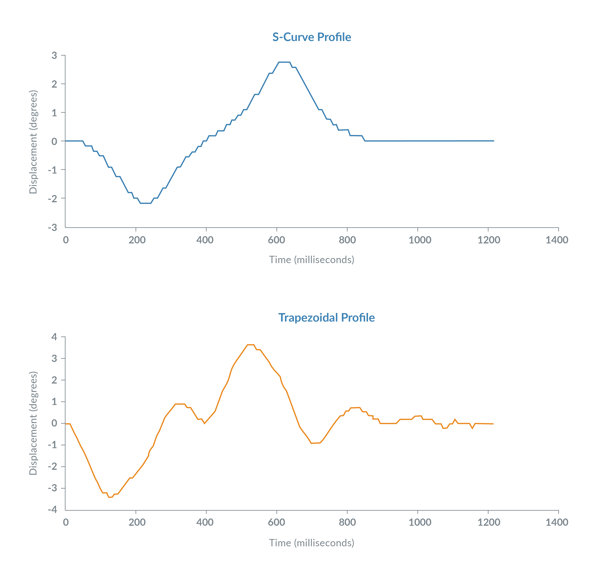
Figure 4: Position Displacement for S-Curve Trajectory Profile versus Trapezoidal Trajectory Profile
|
Trapezoidal Profile
|
S-Curve Profile
|
| Motor move distance | |
|
54,700 counts
|
54,700 counts
|
|
Motor move maximum velocity
|
|
| 1.50 counts/sample time |
1.50 counts/sample time
|
|
Motor move maximum acceleration
|
|
| 0.0035 counts/sample time2 |
0.0035 counts/sample time2
|
|
Motor transfer time
|
|
|
580 mSec
|
750 mSec
|
|
Total load transfer time
|
|
| 1150 mSec |
857 mSec
|
Total load transfer time is defined as the time at which the load position and motor position displacement subsequently remained less than 0.25 degrees for 200 mSec. In this experiment the ION Brushless DC Drive used a standard PID control loop (proportional, Integral, Derivative) to control the position of the BLDC drive motor. The sample time of the trajectory generation and PID control loop was 50 uSec (20,000 Hz).
The traces above were collected and displayed on PMD’s Pro-Motion motion application development software, which is a Windows-based program used for motion system setup, motion system performance analysis, and position loop stability analysis. Today’s modern servo motor controllers and stepper motor controllers come with a wealth of performance measurement features such as this, and Pro-Motion is representative of these types of exercising and motion analysis software tools.
Summary
S-curve trajectory profiles are an important tool for minimizing the effective transfer time of a machine load, particularly when the motor is connected to the load via a compliant mechanism. In the real world, this represents the vast majority of actual motion control applications.
S-curves trajectory profiles work equally well with BLDC motors or DC Brush motors as they do for stepper motors using a microstepping drive control technique. For all of these motor types the trajectory profile of the driven system is tuned to minimize the effective point-to-point transfer time, which is the total time taken for the trajectory move and final settling of the load.
Experimentation with motion capture scope software is the best way to determine how much "S" to add to the trajectory motion profile and get your machine running at peak performance.
PMD Products With S-Curve Profiling
PMD has been producing ICs, drives and boards that provide advanced motion control of Brushless DC, DC Brush and stepper motors for more than thirty years. While different in packaging, all PMD products are controlled by C-Motion, our easy-to-use motion control software library, and are ideal for use in medical, laboratory, semiconductor, robotic, and industrial embedded motion control applications.

MC58113 Series ICs
The MC58113 series of ICs are part of PMD's popular Magellan Motion Control IC Family and provide advanced position control for stepper, Brushless DC, and DC Brush motors. Standard features include FOC (Field Oriented Control), trapezoidal & s-curve profiling, direct encoder & pulse & direction input, and much more. The MC58113 family of ICs are the ideal solution for your next machine design project.
Learn more >>
Magellan Multi-Axis ICs
Magellan Multi-Axis Motion Control ICs feature the latest in profile generation, servo loop closure, and PWM (Pulse Width Modulation) technology and will get your project off to quick and cost-effective start. Available in 1, 2, 3, and 4-axis versions, these flexible, programmable devices control Brushless DC, DC Brush, and step motors and come in compact TQFP (Thin Quad Flat Pack) packages.
Learn more >>
ION/CME N-Series Drives
ION®/CME N-Series Drives are high performance intelligent drives in an ultra-compact PCB-mountable package. In addition to advanced servo and stepper motor control, N-Series IONs provide S-curve point to point profiling, field oriented control, downloadable user code, general purpose digital and analog I/O, and much more. These all-in-one devices make building your next machine controller a snap.
Learn more >>
Prodigy/CME Machine-Controller
Prodigy®/CME Machine-Controller boards provide high-performance motion control for medical, scientific, automation, industrial, and robotic applications. Available in 1, 2, 3, and 4-axis configurations, these boards support DC Brush, Brushless DC, and stepper motors and allow user-written C-language code to be downloaded and run directly on the board. The Prodigy/CME Machine-Controller has on-board Atlas amplifiers that eliminate the need for external amplifiers.
Learn more >>
You may also be interested in:
- The Mathematics of Motion Profiles (Article)
- How to Control Stepper Motors (Article)
- Gantry Control (Motion Application)
- Feedforward In Motion Control (Article)
- High Speed Pick & Place (Motion Application)