
Introduction
When it comes to stepper motor controllers, a new drive technique called closed loop stepper is making everything old new again and winning back machine designers who may have relegated step motors to the category of low cost but low performance.
What makes this technique powerful is that it can use a generic non-custom step motor yet extract much more performance out of it. This is accomplished by adding an encoder and operating the motor as, effectively, a commutated two-phase Brushless DC motor.
The fact that an encoder is needed means that truly low cost applications will not be good candidates for closed loop stepper. But for applications that would otherwise have a Brushless DC motor, closed loop stepper is increasingly being considered as an alternate approach.
In addition to offering a lower cost solution than a comparable Brushless DC motor, closed loop stepper can actually outperform brushless motors in areas such as acceleration rate and torque output. This makes it a candidate for applications such as high speed point-to-point moves, textile equipment, coil winding, high-speed electronic cams, and more.
So how does closed loop stepper work? To answer this we will start with a quick review of traditional step motor control schemes and then dive into how closed loop steppers are different, and what they can do for today's machine designer.
You Had Me At Full Step
Step motors are popular first and foremost because they are easy to use. They do not require an encoder to maintain their position, and unlike DC Brush or Brushless DC motors when used for positioning, they do not require a servo control loop. Their advantages are low cost, high torque output, and brushless operation. Their main drawbacks are vibration, noise, and a limited speed range.
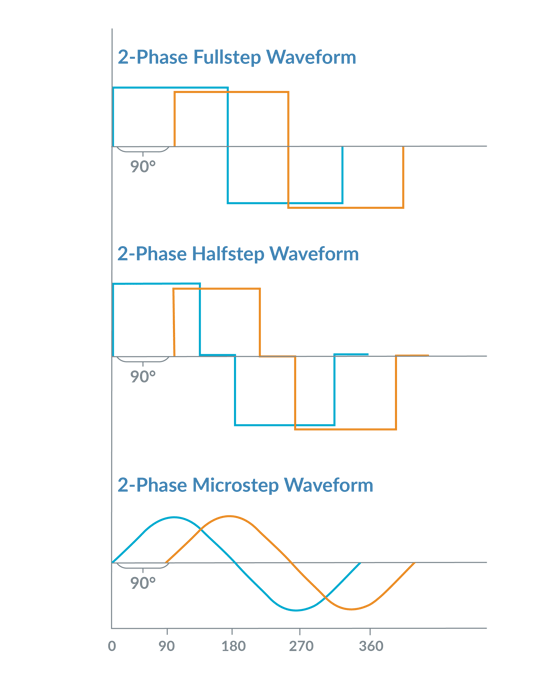
Figure 1: Traditional Step Motor Control Waveforms
Figure 1 shows traditional waveforms for driving a step motor. Stepper motor drivers are a multi-phase device, meaning multiple motor coils are electrically excited to create motion. Most step motors have two phases but more exotic configurations such as 3-phase or 5-phase also exist.
In the world of step motors, the phasing techniques that the amplifiers employ are given special names such as full step, half step, and microstep control. These different techniques refer to the number of power levels that are applied to each motor coil during an electrical cycle. Whichever drive method is used, the motor moves forward or backward when the external controller alters the electrical phasing.
Step motors are usually constructed with 1.8 mechanical degrees per full step (90 electrical degrees). So this means a 1.8 degree stepper has 200 full steps per mechanical rotation. In addition to 1.8 degree step motors, other configurations exist such as .9 degree and 7.2 degrees.
In The Valley Of The B-Field
Now lets look at what's happening inside the motor, and understand in more detail how a traditional stepper motor is operated.
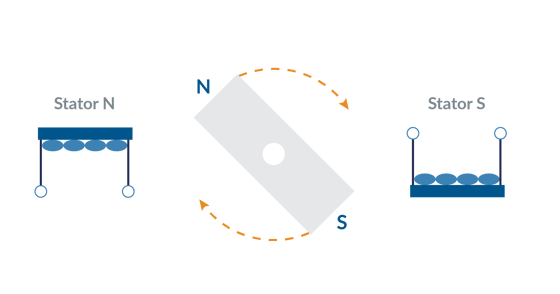
Figure 2: Spinning Bar Magnet Model for Step Motors
Figure 2 provides a simple magnetic model of a stepper motor controller. The rotor can be thought of as a spinning bar magnet that interacts with an externally controlled magnetic field (the stator). The rotational torque generated is zero when the N-S rotor field aligns with the stator N-S magnetic field (also called a B-Field), and maximum when the two fields are at an angle of 90 electrical degrees from each other. It's worth noting that the actual internal construction of a step motor looks nothing like this, but it's still a useful way to understand the motor operation.
When the stator coils are driven with current, a sinusoidal force 'valley' is created which drives the step motor to settle at a specific position. The more current that is driven through the coils, the greater the depth of the force valley. In this force profile of hills and valleys, wherever the curve is horizontal there is no mechanical torque generated, and wherever the curve is the steepest the generated torque is the largest.
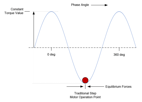
Figure 3: Traditional Step Motor Drive Scheme
As the Figure above shows, in a traditional step motor drive scheme the motor settles to the 'bottom' of the force profile. At this point the net rotational motor torque generated is zero because the motor is at an equilibrium point. This explains why position can be maintained in a step motor without an encoder or servo loop.
To create motion, the controller moves this valley forward or backward by changing the stator phase via the external coil connections. The motor rotor than 'falls' forward or backward, maintaining itself at the bottom of the force valley in response. Think of a ball settling to the bottom of a trough.
Desperately Seeking Smoothness
As convenient and simple as this scheme is, it has a number of drawbacks. Here is a quick rundown:
- Indeterminate Accuracy. The actual position of the settled rotor is the sum of the internal equilibrium-restoring force and whatever external forces on the rotor may exist. Therefore in a given application, or for a given load, the exact actual profile path will vary on a small scale.
- Mid-Range Instability. Going back to the ball metaphor, when the phase angle is changed abruptly the rotor will advance but tend to ring around the equilibrium point and finally settle into the new phase angle. Normally this settling process, which happens very rapidly, is not a big problem, but when the natural ringing frequency equals the commanded step rate a phenomenon called mid-range instability can occur which can result in a dramatic reduction in available torque at that specific operating speed.
- Lost Steps. A sufficient external force can push the rotor away from its equilibrium position all the way up and over the force profile curve and into the next valley. This phenomenon is called losing steps and is often a run-away effect once it starts, meaning the rotor falls further and further behind the commanded profile and eventually comes to a halt.
- Excess Heat. To combat the phenomenon of lost steps the motor is operated at a torque level sufficient to handle the worst-case motion profile. This means at all other times the programmed torque is higher than is actually needed, generating excess heat.
- Noise. Step motors are noisy during motion for a few reasons. If a full step or half step drive scheme is used, the square edges of these coil drive signals excite resonances (read that noise) in the rotor. Another reason is the large number of electrical cycles per mechanical rotation. Just moving the rotor forwards or backwards requires the controller to constantly cycle the command voltages up and down for each phase, which induces noise in the coils and therefore the motor.
- Vibration. All of the factors listed above for noise can also generate vibration. But particularly with a microstepping drive there is a phenomenon that may generate little noise but can create a fair amount of vibration. Due to the geometry of the stator/rotor teeth (a feature of all stepper motor drivers) and peculiarities of the resultant B-fields, the relationship of drive signals to translated motion is never perfect. In other words a plot of commanded position and actual measured position is not an exact straight line. This phenomenon results in rhythmic vibration during motion.
- Low Top Speed. To position accurately step motors move only a small amount for a corresponding advancement of the coil command waveform. A standard 1.8 degree stepper motor requires 50 complete electrical cycles per single mechanical rotation. By comparison a four-pole Brushless DC motor requires just two electrical cycles per mechanical rotation. Motor coil inductance limits how fast the phasing can be changed, and therefore step motors tend to have much lower maximum speeds then Brushless DC motors.
You Had Me At Closed Loop Stepper
Now let's delve into the closed loop stepper technique, sometimes also called closed loop stepper operation (a term that is a bit ambiguous because it is also used to describe a traditional step motor control scheme that uses an encoder to verify the final position thereby 'closing' the loop).
Closed loop stepper operation is different in three key ways from regular stepper motor operation.
- The first is that it requires an encoder to be attached to the step motor, one with a fairly high resolution. For standard 1.8 degree step motors you will want an encoder with no less than 2,000 counts per mechanical rotation, and for 7.2 degree step motors 500 is a bare minimum.
- The second difference is that closed loop stepper operation runs the motor like a Brushless DC motor and commutates the phase angle using the actual encoder position rather than the commanded position. Redrawing our force diagram, the figure below shows how commutated phasing means the stepper motor is operated at the steepest part of the force valley rather than at the equilibrium point.
- The third difference is that rather than being constant, the height and phase angle of the waveform are continuously varied based on the output of a position PID loop, which is used to servo on the commanded position. Again, this is the same as how a Brushless DC motor is operated.
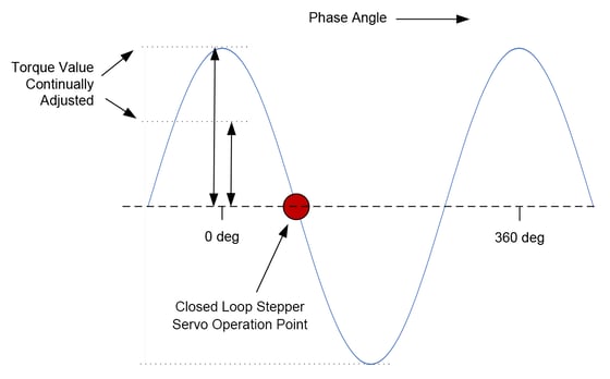
Figure 4: Closed Loop Stepper Operation Point
What are the advantages of operating a step motor this way? There are many:
- No Lost Steps. One immediate advantage is that losing steps is no longer a concern. Operated as a servo motor, the encoder determines the location of the step motor and so the problem of losing steps no longer applies.
- Less Heat. A second advantage is that closed loop stepper operation runs the motor more efficiently, which means less heat generated in the motor. Commutated motors output just the amount of torque needed to achieve a desired motion profile, while traditionally controlled stepper motors are driven at a large constant current that must be sufficient to handle the worst-case motion.
- Accuracy. Accuracy here has two dimensions. Since the encoder explicitly measures the location of the motor, the vagaries of determining the actual rotor settling position that come with a traditional step motor drive are eliminated. The second is that the positioning accuracy becomes unlinked from the motor's degrees per step rating (for example 1.8 degs/step) and the resolution of the microstepping scheme. With a closed loop stepper, the theoretical position resolution is determined solely by the resolution of the encoder, and therefore the same motor could achieve 2,000 resolvable locations per rotation or 1,000,000 resolvable locations depending on the encoder used.
- Velocity Smoothness. Another significant advantage is improved velocity smoothness. Because a traditional stepper motor controller doesn't explicitly measure and control the rotor position, the rotor angle tends to bounce around a bit as it is influenced by external forces. The same motor operated in closed loop stepper mode can achieve much more accurate velocity tracking.
- Noise. With the closed loop stepper technique the motor generates much less noise than a full step or half step drive, and even less noise than a microstepping drive. While not as quiet as a typical Brushless DC motors, closed loop stepper pretty well kills the classic step motor noise problem.
You may also be interested in: Servo Motor Noise and How to Fix It
We're Gonna Need A Bigger Algorithm
The control scheme used with the closed loop stepper looks quite different than the control scheme used with traditional open loop step motor controllers. These traditional controllers often use relatively simple current control techniques such as fixed off-time PWM (Pulse Width Modulation) and do not explicitly command the current during all phases of the motor's electrical cycle. In particular, to decrease the current in the coil an uncontrolled decay mode (sometimes selectable as fast decay or slow decay) is used.
While good-enough for most traditional stepper motor controllers, this will not work well for closed loop stepper controllers. Closed loop stepper controllers instead borrow the control schemes used with a Brushless DC motor, and explicitly control current through all phases of the generated waveform.
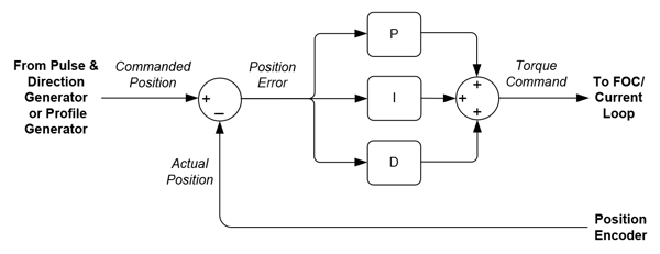
Figure 5: PID Control Loop
There are three overall elements to this control scheme; a position PID loop, a current loop, and a switch mode amplifier and current sense controller. As shown in the figure above the PID loop inputs a commanded position, either from an external pulse & direction source or an internal profile generator, and uses the measured encoder position to generate a position error, and, after filtering via the PID, a current command.
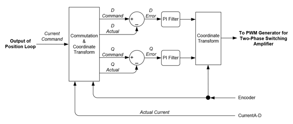
Figure 6: FOC Current Loop Diagram
Current control can be accomplished in a few ways, but increasingly Field Oriented Control (FOC) is used even for step motors. While often associated with Brushless DC motor control, FOC has significant benefits when controlling step motors which include higher top speed and more efficient operation. Figure 6 illustrates the control flow of the FOC scheme. The output of the FOC algorithm are the specific PWM commands for each phase of the bridge.
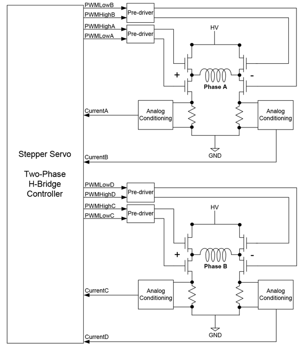
Figure 7: FOC Calculation Flow
The control scheme shown in Figure 7 inputs the PWM commands and outputs explicit high/low switch commands for two bridges, each consisting of four switches in an H-Bridge configuration. In addition to the PWM command itself other parameters of the MOSFET switch such as recharge time and shoot through protection timing are also entered into the controller.
The current is measured using dropping resistors connected to the ground leg of each switch circuit. Leg current sensing is more complicated than fixed off time PWM control, requiring a special algorithm to combine simultaneous measurements from multiple sensors. But it has the benefit that it allows explicit, highly accurate control of the motor coil's current regardless of which sector of the waveform is being executed.
Despite the more advanced motion control technique employed with closed loop stepper versus traditional step motor control, the cost of these electronics have come down so much that the cost of the controls is a diminishing (but not negligible) cost concern. Far from requiring a PLC, module, or entire control board, ICs that can handle all aspects of closed loop stepper control are now readily available on for $20 or less.
Trading Up
For brand new machine designs a closed loop stepper can be incorporated as needed if the performance and economics are beneficial. But for existing designs that already use a traditional pulse & direction scheme and amplifier, the options are fewer.
Luckily new ICs have been released which can help upgrade an existing stepper motor control system for closed loop stepper operation. These products input a pulse and direction input stream and encoder, and provide amplifier outputs compatible with a fully controlled H-bridge current control scheme. Many of these motion control ICs even provide FOC current control.
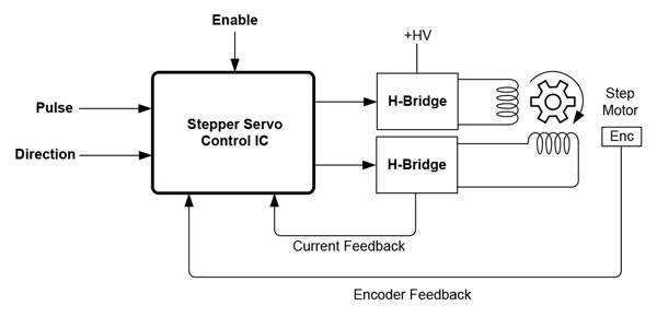
Figure 8: Closed Loop Stepper Pulse and Direction Control
ICs such as this, that let you plug in a 'black box' function for converting a traditional step drive to a closed loop stepper scheme make it relatively easy to upgrade an existing system without also rewriting the profile generation software. These ICs also tend to come with Developer Kits and Exerciser software making it easy to do side by side comparisons of the old system with the new closed loop stepper based system.
Is A Closed Loop Stepper For You?
Hopefully you have enjoyed this technical briefing on the up and coming closed loop stepper control mode. Although it has been on the scene for more than 10 years, it is only in the last few years with the availability of cost effective and high resolution encoders, and dedicated low cost closed loop stepper ICs, that this technique has started to see more wide spread adoption.
Nevertheless, each engineer must determine whether closed loop stepper has a place in their machine design. Because of the need for an encoder, closed loop stepper is not a good match for basic low-cost motion applications where a regular step motor will do. Also, in high speed applications the Brushless DC motor is still the go-to choice.
But in cost sensitive applications that require high torque output and rapid acceleration, step motors controlled with a closed loop stepper technique represent perhaps the best solution on the market right now. These applications include pick & place machines, coil winding, die bonding, embroidery, textile equipment, and others.
Should you use a closed loop stepper in your next design? As always, the details of your application will dictate the correct design choice. But without question, machine designers should be aware of what the closed loop stepper control scheme can offer because it is one of the most important developments in motion control in the last ten years.
PMD Products That Provide Closed Loop Stepper Control
Performance Motion Devices has been producing motion control ICs that provide advanced position and torque control of step motor, DC Brush, and Brushless DC motors for more than twenty-five years. Since that time, we have also embedded these ICs into plug and play modules and boards. While different in packaging, all of these products are controlled by C-Motion, PMD's easy to use motion control language and are ideal for use in pick & place machines, laboratory equipment, liquid handling, and a wide variety of other high performance motion control applications.
Juno Family of ICs
The MC74113 and MC74113N are members of the Juno family of ICs and are perfect for building your own low cost, high performance microstepping or closed loop stepper motor controller. Juno ICs feature FOC (Field Oriented Control), two-phase waveform generation, high/low switching amplifier control signals, leg current sensing, and more. Available in packages as small as 7mm x 7mm and costing $12 in quantity, these ICs are an ideal solution to upgrade your existing pulse & direction controller for closed loop stepper operation, or for starting your next machine design project from scratch.
Learn more >>
MC58113 Series ICs
The MC58113 series of ICs are part of PMD's popular Magellan Motion Control IC Family and provide advanced position control for step motors, BLDC, and DC Brush alike. Standard features include s-curve profiling, FOC (Field Oriented Control), high/low switch signal control, direct encoder & pulse & direction input, and much more. MC58113 ICs can control step motors in a closed loop stepper mode or via a microstepping mode. Whether used for laboratory automation, pump control, pointing systems, or general-purpose automation, the MC58113 family of ICs are the ideal solution for your next machine design.
Learn more >>
ION Digital Drives - Stepper Motor Driver
ION® Digital Drives combine a single axis Magellan IC and an ultra-efficient digital amplifier into a compact rugged package for control of step motors, DC Brush, and Brushless DC motors. In addition to advanced S-curve point to point moves, i2T power management, and downloadable user code, IONs provide closed loop stepper control mode for two-phase step motors as well as safety functions such as over current, over voltage, and over temperature detect. IONs are easy to use plug and play devices that will get your next laboratory equipment, patient treatment, or automation design project up and running in a snap.
Learn more >>
More Motion Control Resources:
- Feedforward in Motion Control - Vital for Improving Positioning Accuracy
- Servo Motor Noise - Common Motion Control Problems and How to Solve Them
- Field Oriented Control (FOC) - A Deep Dive
- Motion Controller Design Architectures - A Deep Dive
- How To Control Stepper Motors
- Mathematics of Motion Control Profiles