The Prodigy®/CME Machine-Controller with pre-installed User Defined Profile Mode (UDPM) is a newly released motion control board that provides high-performance control of DC Brush, Brushless DC, and step motors. Ideal for high precision, high speed positioning motion control, these devices are ideally suited for applications in life sciences, laboratory equipment, semiconductor equipment, mobile robotics, and general automation.
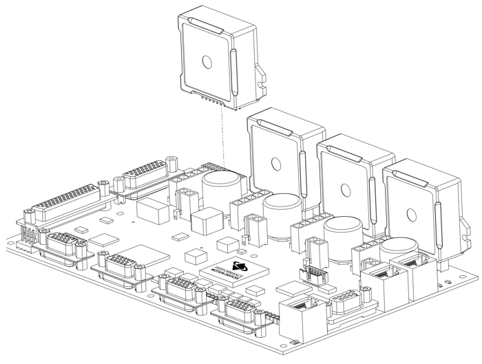
Figure 1: Prodigy® /CME Machine-Controller Board
The figure above shows the Prodigy®/CME Machine-Controller board with Atlas® Digital Amplifiers from Performance Motion Devices, Inc. (PMD) being inserted directly into the board. PMD's Atlas Digital Amplifiers are available for DC Brush, Brushless DC, and step motors and provide up to 500W of output, high performance current control, and extensive safety monitoring including overcurrent, over voltage, and over temperature.
All Prodigy boards are based on PMD’s Magellan® Motion Control IC, which performs high speed motion control functions such as profile generation, servo loop closure, pulse & direction signal generation, and many other real-time functions. The Prodigy/CME Machine-Controller boards include a C-Motion® Engine (CME), which allows the user to load C-language application code directly onto the motion board.
Machine controller boards may be pre-installed with PMD's synchronized contouring profile generation package known as User Defined Profile Mode (UDPM). UDPM is a powerful general-purpose tool for multi-axis synchronized profile generation. It is ideal for applications such as 3-D printing, CNC, label cutting, glue application, inverse kinematic mechanism control, and can also be used for sophisticated single or multi-axis cam profile generation.
Prodigy/CME Machine-Controllers with pre-installed UDPM are the latest addition to PMD's Prodigy motion board family. Other members of the family are available for a PC/104 form factor, a standalone form factor, and come with and without a CME (C-Motion Engine) user downloadable code execution capability. In addition to providing extensive digital and analog I/O, Prodigy boards provide host connectivity via RS832, RS485, CANbus, and Ethernet protocols.
Available Configurations
|
Part Number (P/N)
|
Installed Magellan P/N
|
# of Axes
|
Motor Type
|
|
MC58120
|
1
|
Brushless DC, DC Brush, Step Motor
|
|
|
MC58220
|
2
|
Brushless DC, DC Brush, Step Motor
|
|
|
MC58320
|
3
|
Brushless DC, DC Brush, Step Motor
|
|
|
MC58420
|
4
|
Brushless DC, DC Brush, Step Motor
|
Internal Block Diagram
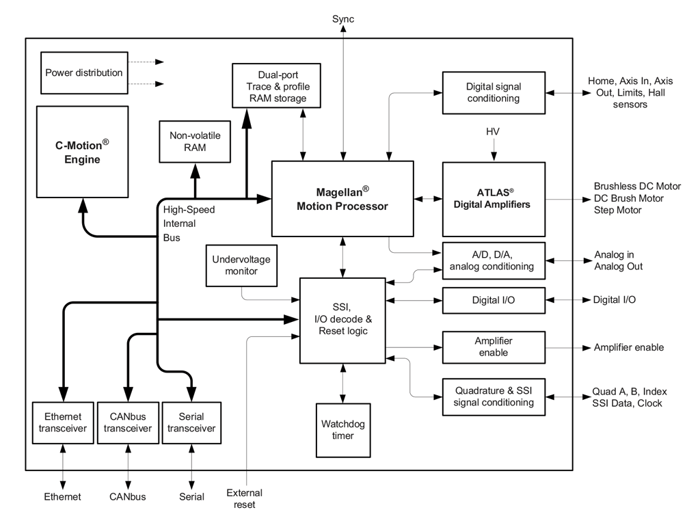
Figure 2: Prodigy/CME Machine Controller Internal Block Diagram
Prodigy/CME Machine-Controller board with User Defined Profile Mode functions can be broken down into several major categories:
Magellan Functions - These are functions which reside in the Magellan Motion Control IC. Included are profile generation, DC brush and Brushless DC servo loop closure, breakpoint processing, and much more. These functions are accessed through the Magellan Motion Control IC’s command set, which allows for sophisticated control of the motion axes and associated hardware.
User Defined Profile Mode - The User Defined Profile Mode (UDPM) Profile Generator uses a novel and powerful approach to trajectory generation consisting of user-loadable lookup tables for each profiled axis that are driven by either an external encoder input, an internal clock signal, or the output velocity envelop from another internal profiled axis. UDPM allows complex multi-dimensional profiling as well as synchronized single axis profiling such as cam profiles.
I/O Functions - These are digital and analog input and output functions. There are 16 general purpose digital channels, consisting of four dedicated inputs, four dedicated outputs, and eight bi-directional. There are eight general purpose +/- 10V analog input channels and eight general purpose +/- 10V output channels.
Communications Functions - The Prodigy/CME Machine-Controller board provides sophisticated communication facilities consisting of two serial ports, a CANbus port, and an Ethernet port.
Atlas Amplifier Functions - The on-board Atlas amplifiers accept motor output commands from the Magellan Motion Control IC and provide high performance current control and amplification for attached step, DC Brush, or Brushless DC motors. There are numerous programmable parameters including current gains, safety parameters, and more.
C-Motion Engine Functions - The C-Motion Engine is a self-contained, high performance code execution unit that allows C-Motion code to be downloaded and executed on the Prodigy/CME Machine-Controller board. It can communicate with various resources on the board including the Magellan Motion Control IC, the board’s serial, CANbus, and Ethernet ports, and other on-board resources such as the dual-ported RAM.
Key Features
Magellan Motion Control IC
The Magellan Motion Control IC in Figure 2 forms the core of the Prodigy/CME Machine-Controller boards. Here is a list of some of the functions provided by the Magellan Motion Control IC:
- Profile generation
- Quadrature encoder processing and index capture
- DC Brush and Brushless DC servo loop closure
- Breakpoint processing
- Trace
- Motion error detection, tracking windows, and axis-settled indicator
- Limit switch processing
Magellan instructions are encoded in packets, which are sent to and from the Magellan Motion Control IC. The Magellan processes these packets, performs requested functions, and returns requested data. Generally speaking, each command packet has its own C-Motion command associated with it.
Example Magellan Instructions
The Magellan instruction set is flexible and powerful. The following very simple example, which sets up and executes a trapezoidal profile, illustrates just a small part of the overall command set. In addition, this small sequence shows the look and feel of C-Motion, PMD’s C-language callable motion interface that handles communications to and from all machine controller board resources.
|
PMDSetProfileMode(&hAxis1, PMDProfileTrapezoidal);
|
// set profile mode to trapezoidal for axis 1
|
|
PMDSetPosition(&hAxis1, 12345);
|
// load a destination position for axis 1
|
|
PMDSetVelocity(&hAxis1, 223344)
|
// load a velocity for axis 1
|
|
PMDSetAcceleration(&hAxis1, 1000)
|
// load an acceleration for axis 1
|
|
PMDSetDeceleration(&hAxis1, 2000)
|
// load a deceleration for axis 1
|
|
PMDUpdate(&hAxis1);
|
// initiate the move
|
hAxis1 is a handle to a structure known as a PMDAxisHandle. There are several different C-Motion structures, and in general they are used to make accessing the Prodigy/CME Machine-Controller boards simpler and more flexible. In particular, by developing code with C-Motion, it is very easy to change the physical location of a PMD axis without any changes to the developed C-Motion code sequences. This is called axis virtualization and is a powerful feature of the C-Motion/Magellan IC system.
Seven-Segment S-Curve Profiling
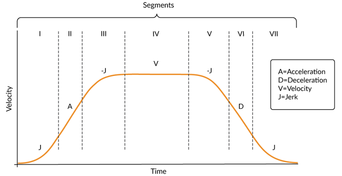
Figure 3: S-curve Profile
While trapezoidal profiles are very common in motion control, the S-curve profile is actually the workhorse for point to point motion because of its greater ability to control the amount of vibrational energy injected into the load. S-curve profiles add a limit to the rate of change of acceleration to the trapezoidal proof. This parameter, known as jerk, specifies the maximum change in acceleration per unit time.
Figure 3 shows a typical S-curve profile. In Segment I, the S-curve profile drives the axis at the specified jerk (J) until the maximum acceleration (A) is reached. The axis continues to accelerate linearly (jerk = 0) through Segment II. The profile then applies the negative value of the jerk to reduce acceleration to 0 during Segment III. The axis is now at maximum velocity (V), at which it continues through Segment IV. The profile will then decelerate in a manner similar to the acceleration stage, using the jerk value first to reach the maximum deceleration (D) and then to bring the axis to a halt at the destination.
PID Position Servo Loop
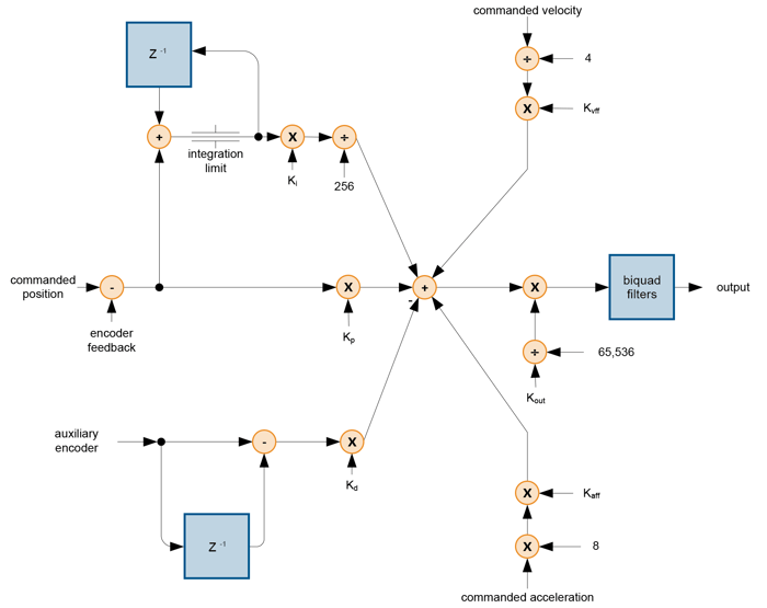
Figure 4: Control Flow Overview of PID Loop
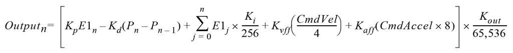
The position servo filter used with the Magellan Motion Control ICs is a proportional-integral-derivative (PID) algorithm, with velocity and acceleration feed-forward terms and an output scale factor. An integration limit provides an upper bound for the accumulated error. A bias value is added to the filter calculation to produce the final motor output command. Figure 4 provides a control flow overview of the PID loop.
The Magellan IC's PID formula, including the scale factor and bias terms, is shown in the following equation:
Servo Tracking Window
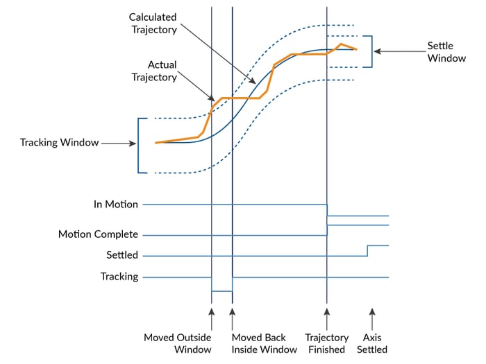
Figure 5: Servo Performance Monitoring
The Magellan Motion Control IC provides a programmable tracking window to monitor servo performance. To initiate this feature the user sets a programmable position error limit within which the axis must remain. Should the axis move outside of the tracking window the Magellan IC can be programmed to report this automatically via hardware signal or via motion packets communication to the host connected to the Prodigy/CME Machine Controller.
The tracking window is particularly useful for external processes that rely on the motor’s correct tracking of the desired trajectory within a specific range. The tracking window may also be used as an early warning for performance problems that do not yet qualify as a motion error.
Field Oriented Control (FOC)
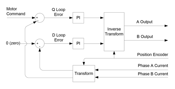
Figure 6: Control Flow of FOC Control
Magellan Motion Control ICs provide several special features for support of Brushless DC motors. These include input of Hall sensors, support for sinusoidal commutation, and support for 2- or 3-phase motors. Atlas-connected Magellan axes, such as are utilized on the Prodigy/CME Machine Controller Board, also provide additional features including Field Oriented Control (FOC).
FOC is a technique for commutating as well as providing current control for Brushless DC motors and step motors. FOC combines the phase input information coming from the encoder or Hall sensors and “re-references” them to what are known as D (direct torque) and Q (quadrature torque) reference frames. This difference in approach provides FOC with performance advantages over sinusoidal commutation at high motor speeds.
User Defined Profile Mode (UDPM)
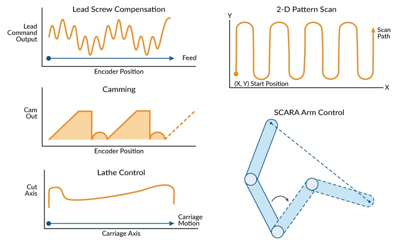
Figure 7: Common Applications Using User-Defined Profile Mode
Prodigy/CME Machine-Controller Boards are available with synchronized continuous path profile generation in one or more axes using a profile mode known as user-defined profile mode. Applications that may benefit from user-defined profile mode include label cutting, 2-D and 3D printing, glue application, metal and wood working, and many others.
SCARA Robot Control Using UDPM
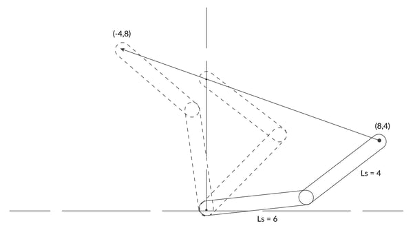
Figure 8: SCARA arm – move from (8, 4) to (-4, 8)
User Defined Profile Mode (UDPM) can be used to control kinematically complex mechanisms such as SCARA arms or other non-orthogonal linkages. Controlling a SCARA robot is not a trivial problem for many motion controllers because the relationship of the motor command to the end effector position involves somewhat complex mathematics. Here are the equations:
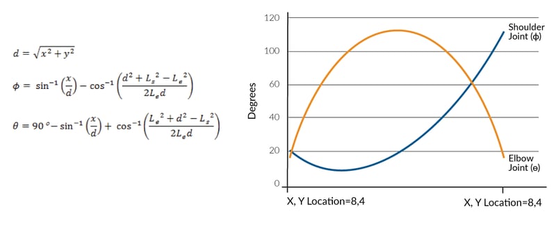
Figure 9: Formulas with Shoulder and Elbow Angles During Straight Line Moves
Using the arm linkage parameters from the arm drawing above, the φ and θ values for a straight line move in XY space from 8, 4 to -4, 8 are shown in the figure to the right of the equations. Unless your motion controller is already set up to control SCARA robots, or unless you can enter arbitrary equations into your controller, most motion controllers will require you to break the above curves into a few straight line segments and then to use a traditional profile generator such as a trapezoidal profile to create an approximation of the curve.
The machine controller's UDPM offers a different approach which is easier to execute and provides a much higher performance result. Because UDPM at the core translates an incoming data set to an output set, the lookup table simply stores a set of recorded Phi (φ) and Theta (θ) command value for each X and Y input value. In this approach the equations are calculated before the motion occurs, and only once to generate the table. Depending on the resolution desired in a typical system a few hundred points might be stored to achieve a smooth translation.
Putting it all together, the animation below shows a SCARA robot move that is linear in the XY space and that uses the UDPM's method of table-based coordinate transformation to command the φ and θ motor commands.
Figure 10: Animation of a SCARA Arm Using UDPM Approach
While the SCARA example above illustrates one successful use of the UDPM approach, much more complicated inverse kinematic relationships can be executed. As long as the desired motor output positions can be calculated for the XYZ space input position, the mechanism can be controlled in the XYZ reference frame automatically by the UDPM system.
Using UDPM
The figure below provides a summary of the control flow of the user-defined profile mode.
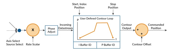
Figure 11: Control Flow Overview of User-Defined Profile Mode
Various operations to load the user defined contour lookup table are provided by the Prodigy/CME Machine-Controller board. This class of commands is referred to as buffer operations and allow the user to load buffer values, read buffer values, and manage buffer wrap if a large object is to be drawn that cannot be stored as a single table in the machine controller's internal memory.
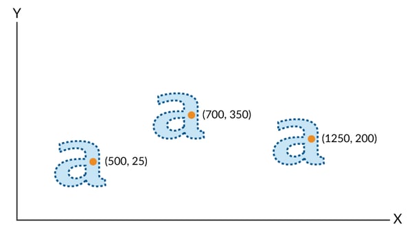
Figure 12: Stored Two-dimensional Contour Drawn in Three Separate Locations
To specify from where within the contour drawing begins both an incoming data stream start index and data stream start value is specified. An example of this is shown in the figure above, where two driven axes have been set up with appropriate user-defined profiles to draw a lower case “a,” and where this object is drawn three separate times beginning at three separate locations.
In each case a direct position profile mode such as trapezoidal or S curve point-to-point is used to locate the driven axes to the correct start locations. Then the user-defined profile parameters are set up and the profile is switched to user-defined to draw each “a” contour.
Atlas Digital Amplifiers
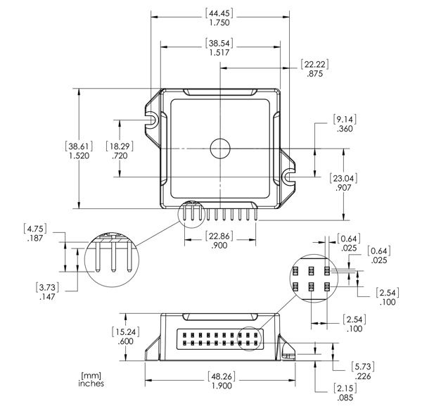 Figure 13: Atlas Digital Amplifiers
Atlas Digital Amplifiers are single-axis devices for torque or voltage-mode control of three-phase Brushless DC motors, and DC Brush motors, and two-phase step motors. They accept a stream of desired torque or voltage values from the Prodigy/CME Machine-Controller board and perform all current loop processing and switching bridge control to continuously drive the motor coils to the specified, commanded torque values.
Atlas amplifiers are packaged in plastic and metal solderable modules and are available in an ultra-compact package size with a total footprint of 1.4 inch2 (9.0 cm2) and a compact package size with a footprint of 2.6 inch2 (16.8 cm2). They come in three power levels; 75 watts, 250 watts, and 500+ watts and utilize standard through-hole pins for all electrical connections.
Atlas amplifiers are provided in both vertical and horizontal mounting configurations, however only the vertical configuration is used for Atlas Amplifiers mounted on the machine controller board. The following table shows the drive capacity of Atlas Digital Amplifiers:
|
Specifications
|
DC Brush Motor
|
Brushless DC Motor
|
Step Motor
|
|
Nominal Supply Voltage
|
12-56 VDC
|
12-56 VDC
|
12-56 VDC
|
|
Continuous Current
|
14.0 ADC
|
10.0 Arms
|
19.0 Arms
|
|
Peak Current (per phase)
|
25.0 A
|
25.0 A
|
25.0 A
|
|
Maximum Continuous Power
|
670 W
|
590 W
|
610 W
|
Communication to/from Atlas occurs via an SPI interface and associated protocol that uses packet-oriented commands to specify various Atlas parameters, and, if desired, request status information from Atlas.
Atlas digital amplifiers provide many advanced control features including user-programmable gain parameters, performance trace, field-oriented control, and I2t current management. Atlas amplifiers are powered from a single supply voltage, and provide automatic protection from overcurrent, undervoltage, overvoltage, overtemperature, and short circuit faults. The following diagram shows the internal block diagram for Atlas Amplifiers.

Appendix I Prodigy/CME Machine-Controller Connector Information
Components and Layout
Figure 14 shows the locations of the principal components of the Prodigy/CME Machine-Controller boards. The user-settable components of the card are listed in the following table:
|
Component
|
Function
|
|
Resistor packs JS1, JS2, and JS3
|
Sets the encoder termination.
|
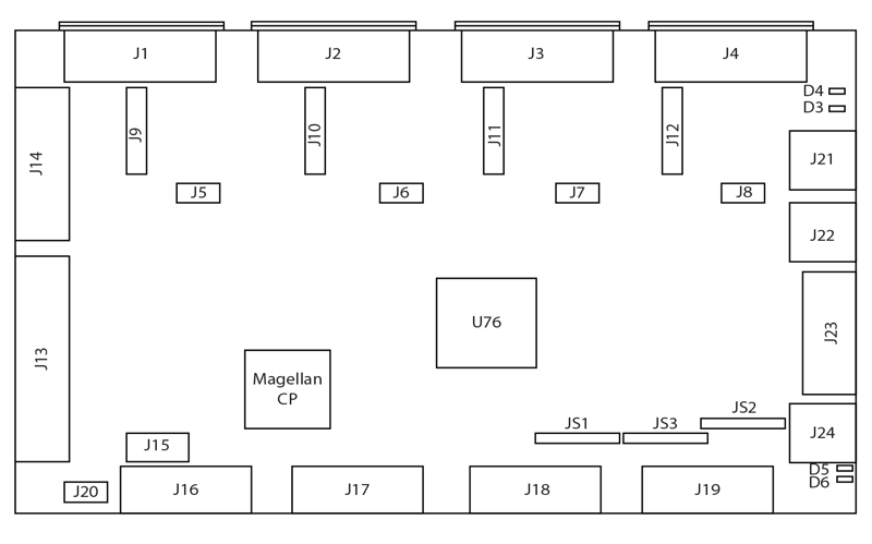
Figure 14: Prodigy/CME Machine-Controller Components and Layout
Connectors
There are 24 user-accessible connectors on the Prodigy/CME Machine-Controller card. See Figure 14 for the specific locations of the connectors on the card. The connectors and their functions are outlined in the following table:
|
Connector Name
|
Connector
|
Functionality
|
|
Axis 1 Atlas
|
J1
|
Provides socket for Axis 1 pluggable Atlas unit.
|
|
Axis 2 Atlas
|
J2
|
Provides socket for Axis 2 pluggable Atlas unit.
|
|
Axis 3 Atlas
|
J3
|
Provides socket for Axis 3 pluggable Atlas unit.
|
|
Axis 4 Atlas
|
J4
|
Provides socket for Axis 4 pluggable Atlas unit.
|
|
Axis 1 Power
|
J5
|
Provides power to the whole card plus Axis 1 Atlas unit. It accepts DC supply in the range of +12 – 56 VDC.
|
|
Axis 2 Power
|
J6
|
Provides power to the whole card plus Axis 2 Atlas unit. It accepts DC supply in the range of +12 – 56 VDC.
|
|
Axis 3 Power
|
J7
|
Provides power to the whole card plus Axis 3 Atlas unit. It accepts DC supply in the range of +12 – 56 VDC.
|
|
Axis 4 Power
|
J8
|
Provides power to the whole card plus Axis 4 Atlas unit. It accepts DC supply in the range of +12 – 56 VDC.
|
|
Axis 1 Motor Drive
|
J9
|
Provides direct motor control signals for Axis 1.
|
|
Axis 2 Motor Drive
|
J10
|
Provides direct motor control signals for Axis 2.
|
|
Axis 3 Motor Drive
|
J11
|
Provides direct motor control signals for Axis 3.
|
|
Axis 4 Motor Drive
|
J12
|
Provides direct motor control signals for Axis 4.
|
|
General I/O
|
J13
|
Provides the following general I/O interfaces to the board: 8 channels of bi-directional digital I/O; 4 channels of digital inputs; 4 channels of digital outputs; 8 channels of differential analog.
|
|
Amplifier I/O
|
J14
|
Provides amplifier enable outputs for 4 axes. Provides 8 AnalogOutput signals for controlling external amplifiers or general purpose ±10V analog output. Provides AxisIn and AxisOut connections for all four axes.
|
|
Expansion
|
J15
|
Provides synchronization of multiple Prodigy Machine-Controller boards within a single system.
|
|
Axis 1 Feedback
|
J16
|
Provides differential or single-ended motor encoder feedback signals such as Quad A/B, Index, Hall A/B/C, PosLim and NegLim for Axis1.
|
|
Axis 2 Feedback
|
J17
|
Provides differential or single-ended motor encoder feedback signals such as Quad A/B, Index, Hall A/B/C, PosLim and NegLim for Axis2.
|
|
Axis 3 Feedback
|
J18
|
Provides differential or single-ended motor encoder feedback signals such as Quad A/B, Index, Hall A/B/C, PosLim and NegLim for Axis3.
|
|
Axis 4 Feedback
|
J19
|
Provides differential or single-ended motor encoder feedback signals such as Quad A/B, Index, Hall A/B/C, PosLim and NegLim for Axis4.
|
|
+5V Power
|
J20
|
Provides logic power to the board when HV1 is not available.
|
|
CAN1, CAN2
|
J21, J22
|
RJ45 connector that provide connection to a CAN 2.0B network.
|
|
Serial
|
J23
|
DB-9 serial port for RS232 or RS485 connections.
|
|
Ethernet
|
J24
|
RJ45 connector that provide connection to an Ethernet TCP/IP network.
|
Atlas Connector
The Atlas Connector (J1 – J4) is the socket that accepts Atlas, the vertical single-axis digital amplifier unit.
Axis 1 Atlas SocketPin
|
Pin
|
Connection
|
Description
|
|
1
|
GND
|
Power return for HV1, Motor A, Motor B, Motor C and Motor D.
|
|
2
|
GND
|
Power return for HV1, Motor A, Motor B, Motor C and Motor D.
|
|
3
|
HV1
|
DC power to axis 1 Atlas module, referenced to GND.
|
|
4
|
HV1
|
DC power to axis 1 Atlas module, referenced to GND.
|
|
5
|
Motor A1
|
Axis 1 motor output signal A.
|
|
6
|
Motor A1
|
Axis 1 motor output signal A.
|
|
7
|
Motor B1
|
Axis 1 motor output signal B.
|
|
8
|
Motor B1
|
Axis 1 motor output signal B.
|
|
9
|
Motor C1
|
Axis 1 motor output signal C.
|
|
10
|
Motor C1
|
Axis 1 motor output signal C.
|
|
11
|
Motor D1
|
Axis 1 motor output signal D.
|
|
12
|
Motor D1
|
Axis 1 motor output signal D.
|
|
13
|
~Enable1
|
An active-low enable signal.
|
|
14
|
FaultOut1
|
FaultOut1 provides programmable fault indication.
|
|
15
|
NC
|
Not Connected.
|
|
16
|
GND
|
Ground return for ~Enable, FaultOut, SPI or pulse & direction signals.
|
|
17
|
~SPICS1
|
Atlas SPI bus slave select1.
|
|
18
|
SPIS1
|
Atlas SPI bus master output, slave input.
|
|
19
|
SPICLK19
|
Atlas SPI bus serial clock.
|
|
20
|
SPISO
|
Atlas SPI bus master input, slave output.
|
Power ConnectorFor each Atlas unit installed on the Prodigy/CME Machine-Controller card, there will be a dedicated 2 pin HV power connector that accepts input voltage in the range of +12 – 56VDC. J5, J6, J7 and J8 are used to provide power to each Atlas unit. Molex 4.20mm Pitch Mini-Fit plus HCS series, single row, vertical, Power Terminal Headers are used for the 2-pin power connectors.
Note that there is a +5V power connector (J20) on the board. Users can power the board with +5V supply when HV1 is not available. However, this will not power the Atlas modules. When HV1 is present, the +5V supply via J20 should not be used. J20 uses the Molex 3.00 Pitch Micro-Fit Header, 2-signal, single row, vertical connector.
Axis 1 Power Connector
|
Pin
|
Connection
|
Description
|
|
J5
|
||
|
1
|
HVI
|
Provides DC power to the card and Axis 1 Atlas module.
|
|
2
|
GND
|
Ground
|
Feedback Connector
The Feedback Connector (J16 – J19 in Figure 14) provides connections to various motor feedback signals. The Feedback Connector uses the 15-pin high density DB connector, which can be connected to PMD Cable-5005-01. Please refer to Section 3.4, “Cables” for detailed information on Prodigy/CME Machine-Controller cable specifications.
For Brushless DC motors, it also connects the Hall effect signals typically used to commutate the motor. The Halls are not used with the DC brush or step motors.
Axis 1 Feedback Connector
|
Pin
|
Connection
|
Description
|
|
J16
|
||
|
1
|
QuadA1+
|
Axis 1 Quadrature A+ encoder input.
|
|
2
|
QuadA1-
|
Axis 1 Quadrature A- encoder input.
|
|
3
|
QuadAB+
|
Axis 1 Quadrature B+ encoder input.
|
|
4
|
QuadB1-
|
Axis 1 Quadrature B- encoder input.
|
|
5
|
GND
|
Ground
|
|
6
|
Index1+
|
Axis 1 Index+ input.
|
|
7
|
Index1-
|
Axis 1 Index- input.
|
|
8
|
HallA1
|
Axis 1 Hall A input.
|
|
9
|
HallB1
|
Axis 1 Hall B input.
|
|
10
|
HallC1
|
Axis 1 Hall C input.
|
|
11
|
Home1
|
Axis 1 Home input.
|
|
12
|
PosLim1
|
Axis 1 Positive direction limit switch input.
|
|
13
|
NegLim1
|
vAxis 1 Negative direction limit switch input.
|
|
14
|
Vcc
|
+5V
|
|
15
|
GND
|
Ground
|
Motor Drive Connector
The Motor Drive connectors (J9 – J12) provide motor output signals for use with Brushless DC, DC Brush, or step motors. These are Molex 4.20mm Pitch Mini-Fit Plus HCS series, single row, vertical connectors.
Axis 1 Motor Connector
|
Pin
|
Connection
|
Description
|
|
J9
|
||
|
1
|
Motor A1
|
Axis 1 motor output signal A.
|
|
2
|
Motor B1
|
Axis 1 motor output signal B.
|
|
3
|
Motor C1
|
Axis 1 motor output signal C.
|
|
4
|
Motor D1
|
Axis 1 motor output signal D.
|
|
5
|
GND
|
Ground
|
General I/O Connector
The General I/O connector provides various I/O connections to the board. There are 8 channels of bi-directional digital I/O; 4 channels of digital input; 4 channels of digital output and 8 channels of differential analog inputs. This is a high-density DB-44 connector.
|
Pin
|
Connection
|
Description
|
Pin
|
Connection
|
Description
|
|
J9
|
|||||
|
1
|
AnalogIn1+
|
Analog input 1+
|
2
|
AnalogIn1-
|
Analog input 1-
|
|
3
|
AnalogIn2+
|
Analog input 2+
|
4
|
AnalogIn2-
|
Analog input 2-
|
|
5
|
AGND
|
Ground for analog signals
|
6
|
AGND
|
Ground for analog signals
|
|
7
|
Reserved
|
Reserved signal
|
8
|
Reserved
|
Reserved signal
|
|
9
|
DigitalIO1
|
Digital input/output 1
|
10
|
DigitalIO2
|
Digital input/output 2
|
|
11
|
DigitalIO3
|
Digital input/output 3
|
12
|
GND
|
Ground
|
|
13
|
DigitalOut1
|
Digital output 1
|
14
|
DigitalOut2
|
Digital output 2
|
|
15
|
DigitalOut3
|
Digital output 3
|
16
|
AnalogIn3+
|
Analog input 3+
|
|
17
|
AnalogIn4+
|
Analog input 4+
|
18
|
AnalogIn5+
|
Analog input 5+
|
|
19
|
AnalogIn6+
|
Analog input 6+
|
20
|
AnalogIn7+
|
Analog input 7+
|
|
21
|
AnalogIn8+
|
Analog input 8+
|
22
|
AGND
|
Ground for analog signals
|
|
23
|
Reserved
|
Reserved signal
|
24
|
Reserved
|
Reserved signal
|
|
25
|
DigitalIO4
|
Digital input/output 4
|
26
|
DigitalIO5
|
Digital input/output 5
|
Amplifier I/O Connector
The Amplifier I/O connector provides various amplifier-related signals including amplifier enable outputs, 8 AnalogOutput signals, AxisIn, and AxisOut signals. This is a high density DB-26 connector.
|
Pin
|
Connection
|
Description
|
Pin
|
Connection
|
Description
|
|
J14
|
|||||
|
1
|
AmpEnable1
|
Axis 1 amplifier enable signal
|
2
|
AmpEnable2
|
Axis 2 amplifier enable signal
|
|
3
|
GND
|
Ground
|
4
|
AxisIn1
|
Axis 1 AxisIn input
|
|
5
|
AxisIn2
|
Axis 2 AxisIn input
|
6
|
AGND
|
Ground for analog signals
|
|
7
|
AnalogOut1
|
Analog output 1
|
8
|
AnalogOut2
|
Analog output 2
|
|
9
|
AnalogOut3
|
Analog output 3
|
10
|
AmpEnable3
|
Axis 3 amplifier enable signal
|
|
11
|
AmpEnable4
|
Axis 4 amplifier enable signal
|
12
|
GND
|
Ground
|
|
13
|
AxisIn3
|
Axis 3 AxisIn input
|
14
|
AxisIn4
|
Axis 4 AxisIn input
|
|
15
|
AnalogOut4
|
Analog output 4
|
16
|
AnalogOut5
|
Analog output 5
|
|
17
|
AnalogOut6
|
Analog output 6
|
18
|
AGND
|
Ground for analog signals
|
|
19
|
AxisOut1
|
Axis 1 AxisOut output
|
20
|
AxisOut2
|
Axis 2 AxisOut output
|
|
21
|
AxisOut3
|
Axis 3 AxisOut output
|
22
|
AxisOut4
|
Axis 4 AxisOut output
|
|
23
|
GND
|
Ground
|
24
|
AGND
|
Ground for analog signals
|
|
25
|
AnalogOut7
|
Analog output 7
|
26
|
AnalogOut8
|
Analog output 8
|
Absolute Maximum Ratings
|
HV voltage range:
|
0V to +60V
|
|
+5V voltage range:
|
-0.3V to +5.5V
|
|
Storage Temperature:
|
-20 to +150 C
|
Environmental and Electrical Ratings
|
Storage temperature:
|
-40 to +125 degrees C (-40° F to +257° F)
|
|
Operating temperature:
|
0 to +70 degrees C (32° F to +158° F)
|
|
HV power requirement:
|
+12V to + 56V operating range
|
|
Optional +5V requirement:
|
4.75V to 5.25V operating range
|
|
Analog (DAC) output range:
|
-10.0V to +10.0V, ± 3mA min/axis, short circuit protected
|
|
Analog input range:
|
-10.0V to +10.0V, 80.4 KOhm input impedance
|
|
Digital I/O voltage range:
|
0V to 5V, TTL thresholds, inputs pulled up to 5V through 4.7 kOhm resistors
|
|
Digital outputs drive capacity:
|
DC output source or sink current: ± 50mA
|
|
CAN communications:
|
2.0B compliant, non-isolated, 1 Mbps
|
|
Serial communications:
|
RS232 signaling or RS485 Full or Half Duplex (data only)
|
|
Ethernet communications:
|
10/100BASE-TX (10/100 Mbps)
|
Mechanical Dimensions
The size of the board is 7.80” L x 4.88” W.
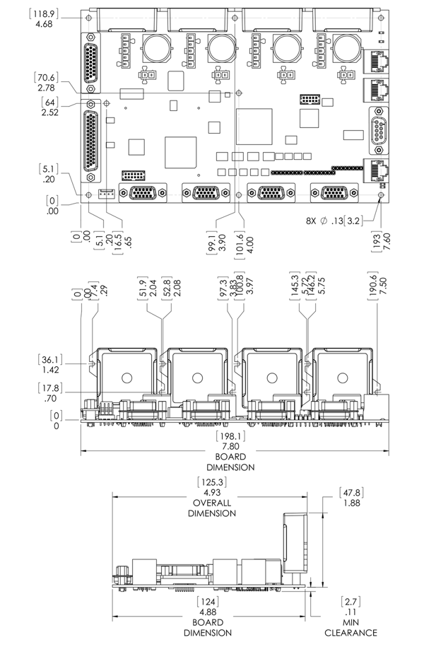
Figure 15: Prodigy/CME Machine-Controller Mechanical Dimensions
L-Bracket Mechanical Dimensions
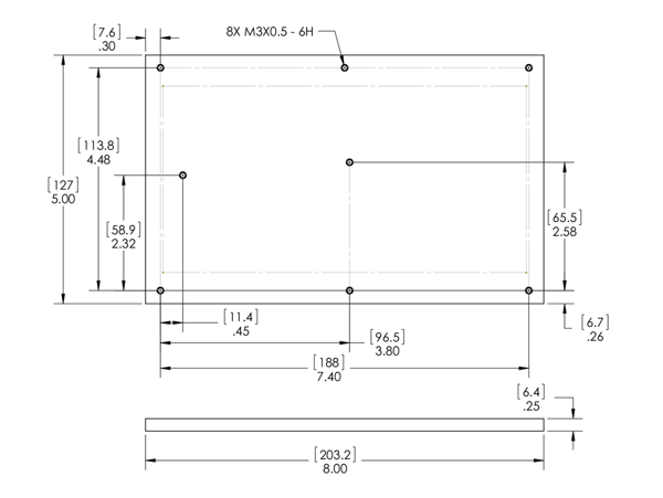
Figure 16a: Prodigy/CME Machine-Controller Base Mechanical Dimensions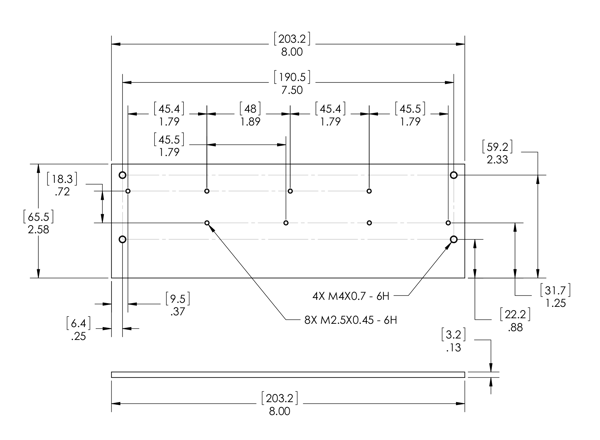
Figure 16b: Prodigy/CME Machine-Controller Vertical Plate Mechanical Dimensions
Additional Resources
- Prodigy/CME Machine-Controller Board Datasheet
- Prodigy/CME Machine-Controller User Guide
- Prodigy/CME Machine-Controller Developer Kit User Manual
- Prodigy Family Motion Control Board Developer Kits
- PMD Resource Center