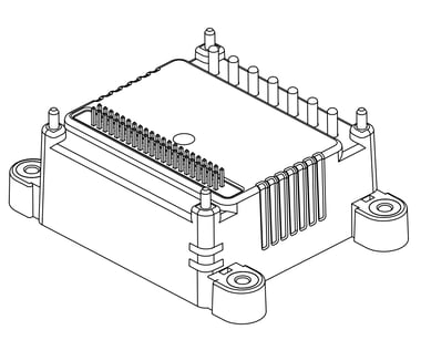
Figure 1: ION/CME N-Series Digital Drive from Performance Motion Devices, Inc.
The ION®/CME N-Series Digital Drives are a family of single-axis motion controllers with integrated power electronics and network communications. Various models are available to drive DC Brush, Brushless DC, and step motors. Their very compact size, range of power output levels, and high level of connectivity make them ideally suited for applications in life sciences, laboratory equipment, semiconductor equipment, mobile robotics, and general automation.
ION N-Series Drives are based on PMD’s Magellan® Motion Control IC and perform profile generation, encoder position feedback, position servo compensation, step motor stall detection, brushless DC motor commutation, microstep generation, digital current/torque control, and more. All members of the ION family have integrated, high power drive stages which fully protect from overcurrent, undervoltage, overvoltage, overtemperature, and short-circuit faults.
N-Series ION host communication options include Ethernet, CAN, RS232/RS485, and SPI (Serial Peripheral Interface). Each drive also supports an additional CAN and SPI expansion network for connecting to other N-Series IONs or to other peripherals. All ION/CME N-Series Drives include a C-Motion® Engine, allowing user application code to be downloaded and executed directly in the drive, along with NVRAM memory and trace memory for the permanent and temporary storage of control parameters and performance trace results.
The N-Series IONs are PCB (printed circuit board) mounted and are packaged in a rugged plastic and metal solderable module measuring 1.48" x 1.48" x .66" (37.6 mm x 37.6 mm x 16.8 mm). They come in three power levels; 75 watts, 350 watts, and 1,000 watts and utilize a 44 pin (2 x 22) 50-mil header for signal connections and a 7-pin high current connector for the DC bus and motor connections.
Available Configurations
There are 36 different ION/CME N-Series Digital Drives in all, consisting of the combinations of four motor types (step motor, Brushless DC, DC Brush, Multi-Motor), three host interfaces (Serial, CAN/SPI, Ethernet), and three power levels (low, medium, high). Note that multi-motor units allow the motor type, either Brushless DC, DC Brush, or step motor, to be user programmed.
The following table shows the available N-Series ION part numbers:
| PART NUMBERS | HOST INTERFACE | POWER LEVEL | VOLTAGE | MOTOR TYPE |
| STEP MOTOR | ||||
| DD441S0056/02 | Serial | Low (75W) | 12-56V | Step Motor |
| DD441S0056/06 | Serial | Medium (350W) | 12-56V | Step Motor |
| DD441S0056/18 | Serial | High (1,000W) | 12-56V |
Step Motor |
| DD441C0056/02 | CAN/SPI | Low (75W) | 12-56V | Step Motor |
| DD441C0056/06 | CAN/SPI | Medium (350W) | 12-56V | Step Motor |
| DD441C0056/18 | CAN/SPI | High (1,000W) | 12-56V | Step Motor |
| DD441D0056/02 | Ethernet | Low (75W) | 12-56V | Step Motor |
| DD441D0056/06 | Ethernet | Medium (350W) | 12-56V | Step Motor |
| DD441D0056/18 | Ethernet | High (1,000W) | 12-56V | Step Motor |
| BRUSHLESS DC | ||||
| DD431S0056/02 | Serial | Low (75W) | 12-56V | Brushless DC |
| DD431S0056/06 | Serial | Medium (350W) | 12-56V | Brushless DC |
| DD431S0056/18 | Serial | High (1,000W) | 12-56V | Brushless DC |
| DD431C0056/02 | CAN/SPI | Low (75W) | 12-56V | Brushless DC |
| DD431C0056/06 | CAN/SPI | Medium (350W) | 12-56V | Brushless DC |
| DD431C0056/18 | CAN/SPI | High (1,000W) | 12-56V | Brushless DC |
| DD431D0056/02 | Ethernet | Low (75W) | 12-56V | Brushless DC |
| DD431D0056/06 | Ethernet | Medium (350W) | 12-56V | Brushless DC |
| DD431D0056/18 | Ethernet | High (1,000W) | 12-56V | Brushless DC |
| DC BRUSH | ||||
| DD411S0056/02 | Serial | Low (75W) | 12-56V | DC Brush |
| DD411S0056/06 | Serial | Medium (350W) | 12-56V | DC Brush |
| DD411S0056/18 | Serial | High (1,000W) | 12-56V | DC Brush |
| DD411C0056/02 | CAN/SPI | Low (75W) | 12-56V | DC Brush |
| DD411C0056/06 | CAN/SPI | Medium (350W) | 12-56V | DC Brush |
| DD411C0056/18 | CAN/SPI | High (1,000W) | 12-56V | DC Brush |
| DD411D0056/02 | Ethernet | Low (75W) | 12-56V | DC Brush |
| DD411D0056/06 | Ethernet | Medium (350W) | 12-56V | DC Brush |
| DD411D0056/18 | Ethernet | High (1,000W) | 12-56V | DC Brush |
| MULTI MOTOR | ||||
| DD481S0056/02 | Serial | Low (75W) | 12-56V | Multi Motor |
| DD481S0056/06 | Serial | Medium (350W) | 12-56V | Multi Motor |
| DD481S0056/18 | Serial | High (1,000W) | 12-56V | Multi Motor |
| DD481C0056/02 | CAN/SPI | Low (75W) | 12-56V | Multi Motor |
| DD481C0056/06 | CAN/SPI | Medium (350W) | 12-56V | Multi Motor |
| DD481C0056/18 | CAN/SPI | High (1,000W) | 12-56V | Multi Motor |
| DD481D0056/02 | Ethernet | Low (75W) | 12-56V | Multi Motor |
| DD481D0056/06 | Ethernet | Medium (350W) | 12-56V | Multi Motor |
| DD481D0056/18 | Ethernet | High (1,000W) | 12-56V | Multi Motor |
Developer Kits
N-Series IONs are available in a developer kit configuration. Each developer kit comes with the specified N-Series ION soldered onto an interconnect board and mounted on a baseplate/heatsink for convenient use on a bench top surface.

Figure 2: The ION/CME N-Series Digital Drive Developer Kit
The DK interconnect boards measure approximately 3.25" x 2.75" and are compact enough that if not used on a bench top, they are suitable for mounting directly on the actual machine hardware during prototyping or even for the production application.
For a list of part numbers and available developer kit configurations, refer to Appendix V at the end of this document.
N-Series ION Feature List
General
- Controls Brushless DC, Step Motor, and DC Brush motors
- Three power levels available; 75W, 350W, 1,000W
- 12-56V single DC supply operation
- Magellan Motion Control IC engine provides high-performance positioning, current control, and drive safety features
- User downloadable code allows complete customizability of protocol processing and machine controller behavior
- Host-connected or fully autonomous operation
- Two status indicator LEDs
- Real time clock
- 8 general purpose digital I/Os
- 1 general purpose analog input
Communications
- Four available host connections; Ethernet, Serial, CAN, and SPI (Serial Peripheral Interface)
- Two expansion networks; CAN and SPI for ION to ION communication or communication to other devices and peripherals
- 10/100BASE-T Ethernet
- Support for UDP & TCP protocols with DHCP (Dynamic Host Configuration Protocol)
- RS232 & RS485 asynchronous serial
- CAN FD (backwards compatible with CANbus 2.0)
Motion Control IC
- Advanced PID filter with velocity and acceleration feedforward
- Programmable position & PID loop rate up to 50 μSec
- 50 μSec commutation and current loop rate
- Dual biquad filters
- Autotuning for easy setup and optimal operating performance
- 32KB Internal trace buffer with simultaneous capture of up to four variables
- Incremental quadrature encoder input up to 40.0 Mcounts/sec
- Sin/cos encoder support with up to 16,384 x interpolation factor
- BISS-C and SSI encoder support
- Second (auxiliary) axis of encoder input with quadrature A, B or pulse & direction input
- Hall sensor inputs, two directional limit switches, Index, Home, AxisIn & AxisOut, SynchIn & SynchOut signals
C-Motion Engine
- High speed user code execution module
- Multitasking
- 256 Kbytes of NVRAM user program space
- 256 Kbytes user stack space
- Event manager
- 428 MIPS code execution speed
Amplifier & Safety
- Ultra-efficient fully digital switching power amplifier
- Proprietary current/torque technique provides quiet and efficient motor operation
- Field-oriented control & space vector modulation
- I2t current foldback management
- Selectable 20, 40, 80, or 120 kHz PWM frequency operation
- Brake Input
- FaultOut signal
- Overvoltage, undervoltage, overcurrent, short circuit, and overtemperature monitoring & protection
- Shunt control
Internal Block Diagram
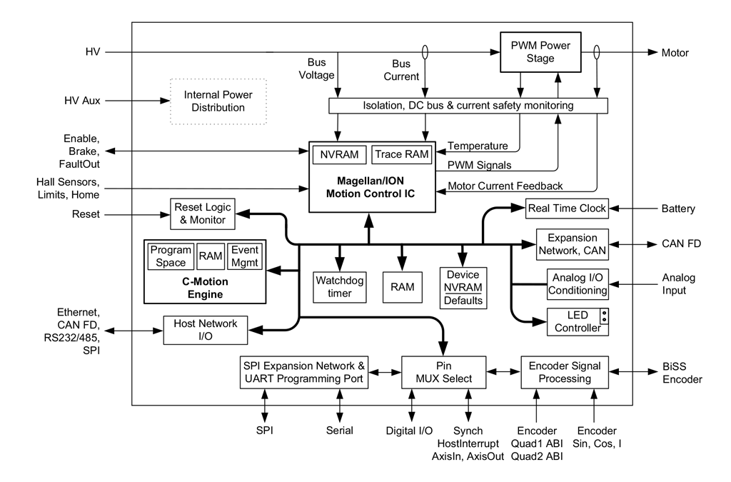
Figure 3: ION/CME N-Series Internal Block Diagram
N-Series ION functions can be broken down into nine overall categories:
Magellan IC Functions - These are functions which reside in the Magellan Motion Control IC. Included are profile generation, DC Brush and Brushless DC servo loop closure, breakpoint processing, current control, PWM signal generation, and much more. These functions are accessed through the Magellan Motion Control IC’s command set, which allows for sophisticated control of the motion axes and associated hardware.
Encoder Functions - These are the functions related to encoder input processing. The encoder formats supported by N-Series IONs are quadrature, pulse & direction, sin/cos, and BiSS-C.
Motion Peripheral Functions - These are the functions directly related to Magellan IC axis signals such as Enable, FaultOut, HostInterrupt, Home, limit switch inputs, Hall inputs, AxisIn & AxisOut, and SynchIn & SynchOut.
I/O functions - These are digital and analog input and output functions. There are 8 general purpose bi-directional digital channels, and there is one general purpose +/- 10V analog input channel.
Communications Functions - The N-Series IONs provide sophisticated communication facilities consisting of one of four host interfaces depending on the specific ION unit type being used: Serial, CAN FD, SPI, or Ethernet. In addition, CAN FD and SPI ports, referred to as expansion networks, are available on every N-Series ION.
Power Stage Functions - The on-board amplifier accepts motor output commands from the Magellan Motion Control IC and provides high-performance amplification and current control for step, DC Brush, or Brushless DC motors.
Drive Safety Functions - ION provides numerous safety and DC bus management functions including detection and protection from over current, over temperature, over/under voltage, shunt control, and more.
C-Motion Engine Functions - The C-Motion Engine is a self-contained, high-performance code execution unit that allows C-Motion code to be downloaded and executed on the N-Series ION. It can communicate with various resources on the board including the Magellan Motion Control IC, the drive’s serial, CAN, Ethernet and SPI ports, and other resources such as the NVRAM.
General Drive Functions - These are functions associated with general drive facilities including non-volatile RAM, reset, a real time clock, LED control, pin muxing, and other functions.
Typical Applications
Network-Connected Drive
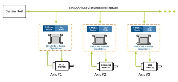
Figure 4: N-Series ION used as Network-Connected Drive
In this application, one or more N-Series IONs connect directly to an RS422, RS485, CAN, Ethernet, or SPI (Serial Peripheral Interface) network and provide control of Brushless DC, DC Brush, or step motors. Commands are sent by the host to each N-Series ION to accomplish the overall machine function. In addition to N-Series IONs other PMD network-attached devices may be added to the network or non-PMD devices as well.
In this configuration downloading user code to the N-Series IONs is optional. Attached N-Series IONs may execute downloaded user code, or may operate by direct command from the host.
Additional hardware needed: The N-Series IONs are powered directly via a single +HV voltage and provide all electrical functionality for this application. The only additional hardware needed is an interconnect board to partition each N-Series ION’s power, motor, and signal connections to appropriate external connectors. This functionality is typically provided via a user-designed interconnect board or via one of the off-the-shelf PMD DK interconnect boards.
Host-Connected Machine Controller
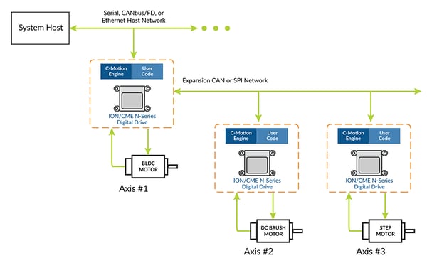
Figure 5: N-Series IONs Used As Host-Connected Machine Controller
In this application one N-Series ION (axis #1) interfaces directly to an RS422, RS485, CAN, Ethernet, or SPI network via its host network interface, and this same ION unit directly controls one or more additional N-Series IONs connected via its expansion CAN or SPI network. User-written application code is downloaded into the host-connected ION's C-Motion Engine. This code processes commands from the host network and generates motion sequences for its own motor axis and the expansion network-attached motor axes to accomplish the desired machine behavior.
Additional hardware needed: The N-Series IONs are powered directly via a single +HV voltage and provide all electrical functionality for this application. The only additional hardware needed is the host network, motor, and peripheral connectors. This functionality is typically provided via a user-designed interconnect board.
Standalone Controller with User Interface
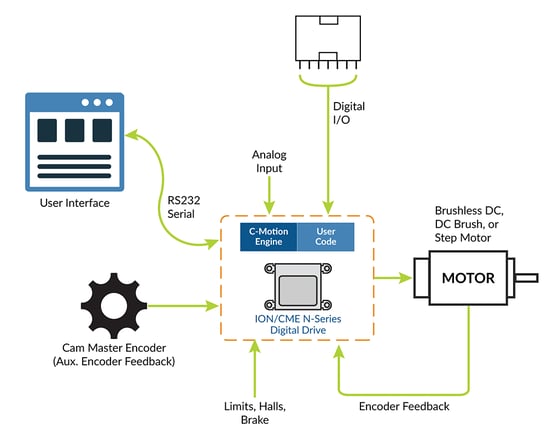
Figure 6: N-Series ION Used as Standalone Controller
In this application, an N-Series ION functions as a complete standalone controller. The Serial N-Series ION connects via its RS232 port to a user interface module which allows an operator to configure and control a cam profile function. The cam master encoder data stream is input via the N-Series ION's auxiliary encoder input. Finally, digital I/Os from a PLC interface directly with the N-Series ION to select the cam profile to execute.
User created and downloaded code executing in the N-Series ION’s C-Motion Engine provides the overall standalone controller functionality including operating the user interface and providing the PLC bit-command processing.
Additional hardware needed: The N-Series ION is powered directly via a single +HV voltage and provides all electrical functionality for this application other than power for the user interface module. The only additional hardware needed are the various connectors to interface to the user interface, encoder, PLC, motor, and motor feedback. This functionality is typically provided via a user-designed interconnect board.
N-Series ION Key Product Features
Magellan Motion Control IC
The Magellan Motion Control IC forms the core of the ION/CME N-Series Digital Drive. Here is a list of some of the functions provided by the Magellan Motion Control IC:
- Profile generation
- Quadrature encoder processing and index capture
- DC Brush and Brushless DC servo loop closure
- Breakpoint processing
- Trace
- Motion error detection, tracking windows, and axis-settled indicator
- Limit switch processing
Magellan instructions are encoded in packets, which are sent to and from the Magellan Motion Control IC. The Magellan processes these packets perform requested functions, and returns requested data. Generally speaking, each command packet has its own C-Motion command associated with it.
Example Magellan Instructions
The Magellan instruction set is flexible and powerful. The following very simple example, which sets up and executes a trapezoidal profile, illustrates just a small part of the overall command set. In addition, this small sequence shows the look and feel of C-Motion, PMD’s C-language callable motion interface that handles communications to and from all machine controller board resources.
| PMDSetProfileMode(&hAxis1, PMDProfileTrapezoidal); | // set profile mode to trapezoidal for axis 1 |
| PMDSetPosition(&hAxis1, 12345); | // load a destination position for axis 1
|
| PMDSetVelocity(&hAxis1, 223344); | // load a velocity for axis 1 |
| PMDSetAcceleration(&hAxis1, 1000); | // load an acceleration for axis 1 |
| PMDSetDeceleration(&hAxis1, 2000); | // load a deceleration for axis 1 |
| PMDUpdate(&hAxis1); | // initiate the move |
hAxis1 is a handle to a structure known as a PMDAxisHandle. There are several different C-Motion structures, and in general, they are used to make accessing the N-Series ION simpler and more flexible. In particular, by developing code with C-Motion, it is very easy to change the physical location of a PMD axis without any changes to the developed C-Motion code sequences. This is called axis virtualization and is a powerful feature of the C-Motion/Magellan IC system.
Seven-Segment S-Curve Profiling
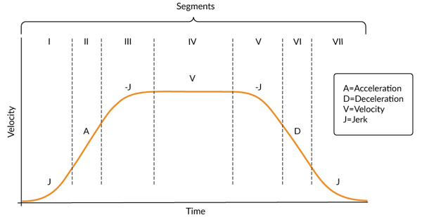
Figure 7: S-curve Profile
While trapezoidal profiles are very common in motion control, the S-curve profile is actually the workhorse for point to point motion because of its greater ability to control the amount of vibrational energy injected into the load. S-curve profiles add a limit to the rate of change of acceleration to the trapezoidal profile. This parameter, known as jerk, specifies the maximum change in acceleration per unit time.
Figure 7 shows a typical S-curve profile. In Segment I, the S-curve profile drives the axis at the specified jerk (J) until the maximum acceleration (A) is reached. The axis continues to accelerate linearly (jerk = 0) through Segment II. The profile then applies the negative value of the jerk to reduce acceleration to 0 during Segment III. The axis is now at maximum velocity (V), at which it continues through Segment IV. The profile will then decelerate in a manner similar to the acceleration stage, using the jerk value first to reach the maximum deceleration (D) and then to bring the axis to a halt at the destination.
Servo Tracking Window
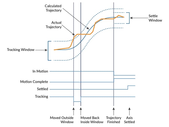
Figure 8: Servo Performance Monitoring
The Magellan Motion Control IC provides a programmable tracking window to monitor servo performance. To initiate this feature the user sets a programmable position error limit within which the axis must remain. Should the axis move outside of the tracking window the Magellan IC can be programmed to report this automatically via hardware signal or via motion packets communication to the host connected to the N-Series ION.
The tracking window is particularly useful for external processes that rely on the motor’s correct tracking of the desired trajectory within a specific range. The tracking window may also be used as an early warning for performance problems that do not yet qualify as a motion error.
Compact, Rugged, PCB-mountable Package
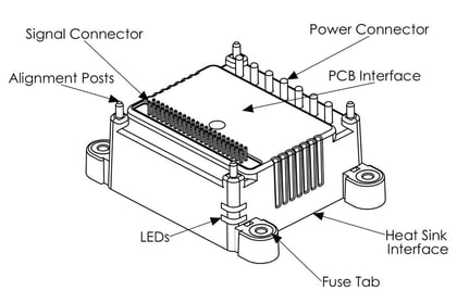
Figure 9: The ION/CME N-Series Digital Drive Operating Layout
The N-Series ION is designed to be used in a wide variety of operating conditions. As shown in Figure 9 it has a robust mechanical design that allows rigid attachment at the two primary interface points: the interface between the N-Series ION and the user PCB, and the interface between the N-Series ION and the heat sink or cold plate.
Attachment at the PCB is accomplished by soldering the PCB to the N-Series Drive’s four mechanical alignment posts. While these posts do not serve an electrical function, they provide a rigid attachment of the PCB to the N-Series ION, and thereby reduce the strain that may occur in the solder connections between the user PCB and the Power and Signal Connectors of the N-Series ION.
Additional elements of the N-Series ION package include two LEDs, one indicating power and the other indicating operating status, and four tabs with threaded M2.5 inserts that utilize a patented "fuse tab" design for additional safety and protection of the internal electronics. The N-Series ION's case isolates the electronics from the external operating environment of the unit. This allows it to be used in harsh environments where contaminants might otherwise cause an electrical failure or out of spec operation.
Substrate Mounting Method
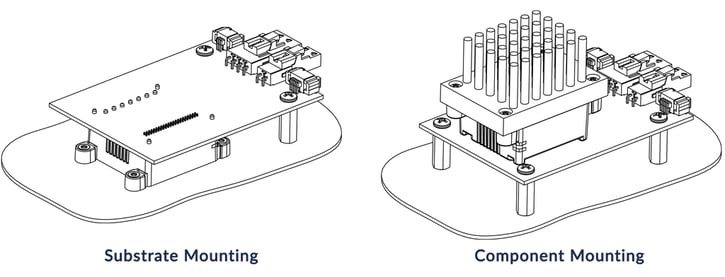
Figure 10: Substrate versus Component Mounting
The N-Series ION's rugged package has been designed to support a new and unique mounting method called substrate mounting. This mounting method along with the opposite approach known as component mounting are shown in Figure 10, which illustrates a simple one axis interconnect board utilizing both mounting approaches for comparison.
With the substrate mounting mode the chassis wall of the device, whether a blood analyzer, wafer handling automation, or a mobile robot, directly anchors the ION unit via four mounting tabs and then supports the user PCB sits on the opposite side of the ION unit. This is convenient because it solves two key problems with one simple mounting method- how to wick away heat and how to mount the machine control PCB.
The alternate approach known as component mounting is most often used in combination with air-cooled heat sinks and may be preferrable when the control board is larger, has a higher number of axes to control, or contains a significant number of elements other than N-Series IONs on it.
High Efficiency Digital Switching Motor Amplifier
The N-Series IONs contain a high-efficiency fully digital MOSFET power stage with PWM (Pulse Width Modulation) control and leg current feedback. A slightly different configuration is used for each motor type:
- DC Brush motors are driven with an H-Bridge consisting of 4 MOSFET switches.
- Brushless DC motors are driven with a 3-phase bridge consisting of 6 MOSFET switches.
- Step motors are driven with two H-Bridges, one for each phase, for a total of 8 MOSFET switches.
The use of 3-phase and H-Bridge topologies provides full 4-quadrant operation.
N-Series IONs use an advanced PWM switching scheme that minimizes the ripple current on the motor windings while maximizing the current loop performance. The PWM frequency is selectable between 20 kHz and 120 kHz to cover a broad range of motor inductance. The fundamental frequency of the ripple current is at twice the PWM frequency and well out of the audible range in all cases.
A representative diagram of the switch and current sense configuration is shown in Figure 11. The diagram shown is for Brushless DC motors, the configuration will be somewhat different for DC Brush and step motors.
Three power output levels are provided which correspond roughly to 75W, 350W, and 1,000W output power. See Appendix II for detailed drive ratings. In addition to highly efficient and powerful motor drive capacity, the N-Series IONs provide several important amplifier and DC voltage related safety features including over voltage, under voltage, overcurrent, and over temperature, along with shunt control for HV protection during deceleration and I2T control for precise control of heating in the actuator and motor being driven.
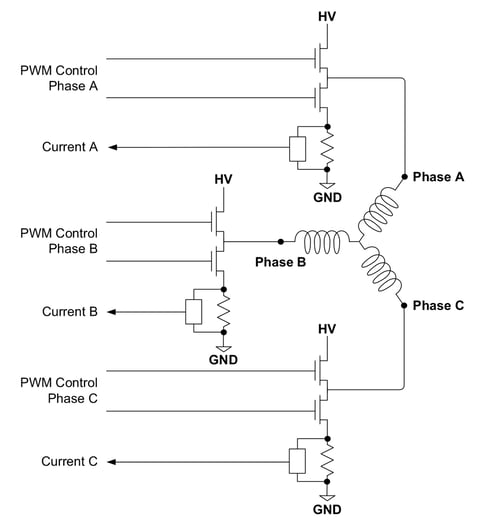
Figure 11: Brushless DC Motor Bridge Configuration
C-Motion Engine
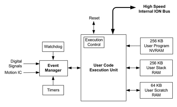
Figure 12: C-Motion Engine Internal Block Diagram
The C-Motion Engine (CME) allows user-written code to be downloaded and executed on the N-Series ION. The C-Motion Engine is a powerful and flexible engine that can be used to:
- Operate N-Series IONs in a standalone mode
- Offload time-critical code from the host to the ION unit
- Communicate via serial, CAN, Ethernet or SPI with a cell controller or other host controller
- Communicate via the expansion SPI and expansion CAN networks to other N-Series IONs or control system peripherals
- Lower system cost by combining functions that would otherwise reside in a separate board or microprocessor.
The CME is connected to other internal N-Series ION resources via a high-speed bus, allowing it to access the Magellan IC, the host communication ports, the expansion network ports, the LEDs, the device default NVRAM, the real time clock, and many other internal N-Series ION resources.
Creating, compiling, downloading, and verifying a user C-Motion application on a N-Series ION is accomplished with the C-Motion Engine development system. The outcome of such a development sequence is a downloadable .bin code image that contains the user application code to be executed by the C-Motion Engine on the N-Series ION.
Downloaded user code executes on the CME at a rate as high as 428 MIPS, although within the code execution unit there is also an internal real-time operating system (RTOS) that utilizes some of these code execution resources to provide functions such as multi-tasking, memory management, and other functions.
Network Communications
N-Series IONs provide four host communication interfaces: Serial, CAN, Ethernet, and SPI (Serial Peripheral Interface). The host interface type of the N-Series ION determines which of these four host interface connections is present in the unit.
All units regardless of host interface type also provide an expansion CAN, an expansion SPI, and a serial programming port interface. This is shown in the following table along with the specific port identifier labels for each interface.
| N-Series ION Unit Type | Host Interface(s) | Expansion CAN | Expansion SPI | Programming Port |
| Serial | RS232 – Serial1, Serial2 RS485 – Serial1 |
ExpCAN | ExpSPI | Serial3 |
| CAN/SPI | HostCAN, Host SPI | ExpCAN | ExpSPI | Serial3
|
| Ethernet | Ethernet | ExpCAN | ExpSPI | Serial3 |
RS232, RS485, UART
N-Series IONs that are of serial host interface type provide asynchronous serial communications in both RS232 and RS485 format.
In RS232 mode two serial ports are supported, referred to as Serial1 and Serial2. Serial1 serves as the host serial interface for the ION unit, while Serial2 serves as an extra general purpose RS232 port. While some applications will not need to use two serial ports, the second port may be useful during C-Motion application code debugging, or to communicate with various serial devices connected to the ION unit.
Settings & default values for Serial1 and Serial2:
| Parameter | Range | Serial1 Default | Serial2 Default |
| Baud rate | 1,200 to 921,600 | 57,600 | 115,200 |
| Baud rate | none, even, odd | none | none |
| Baud rate | 5, 6, 7, 8 | 8 | 8 |
| Baud rate | 1, 2 | 1 | 1 |
In addition to Seria1 and Serial2 a third Serial3 port is offered. This is a UART interface known as the programming port and is most often used during setup when communicating via Pro-Motion, the Windows based setup and application tuning tool.
CAN
The N-Series IONs provide either one or two general purpose CAN ports, both compatible with the CAN FD standard. CAN/SPI type host interface N-Series IONs support a host interface CAN FD port. All N-Series units support an expansion CAN FD port which is useful for networking IONs together and building hierarchical networks that can reduce network traffic bottlenecks.
CAN FD supports two separate baud rates, the nominal baud rate and the data baud rate. This information is summarized in the following table:
| Parameter | Range | Serial1 Default |
| Nominal baud rate | 10,000 to 1,000,000 bps | 1,000,000 |
| Data baud rate | 10,000 to 5,000,000 bps | 1,000,000 |
| Host send address | 0 – 0x800 | 0x580 |
| Host receive address | 0 – 0x800 | 0x600 |
Ethernet
N-Series IONs that are of Ethernet host interface type provide 100 Base-T standard Ethernet communications. Two different Ethernet protocols are supported; TCP (Transmission Control Protocol) and UDP (User Datagram Protocol). TCP is used for primary Ethernet communications to the ION unit, while UDP is typically used for non-critical applications such as data logging, or for the Pro-Motion console window.
| Parameter | Range | Default |
| IPaddress | 0.0.0.0 – 255.255.255.255 | 192.168.2.2 |
| Netmask | 0.0.0.0 – 255.255.255.255 | 255.255.255.0 |
| Gateway | 0.0.0.0 – 255.255.255.255 | 0.0.0.0 |
| PRPListenTCPPort | 0 – 65,535 | 40100 |
SPI (Serial Peripheral Interface)
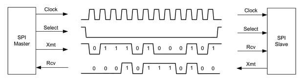
Figure 13: SPI Data Transaction Signals
ION/CME N-Series Digital Drives that are of CAN/SPI host interface type provide an SPI (Serial Peripheral Interface) port for host communications. This SPI port operates as an SPI slave, and is most often used as a connection from another N-Series ION or from an on-board microprocessor. Alternatively, the host SPI port can be used in conjunction with user code stored in the N-Series ION’s C-Motion Engine to execute an application specific protocol.
All N-Series IONs, regardless of host interface type, provide an expansion SPI port. This port functions as an SPI master and supports up to four chip selects allowing communication with up to four separate SPI-connected devices.
Typical uses of the expansion SPI port are connecting to other N-Series IONs and connecting to SPI peripherals such as ADCs (Analog to Digital Converters), DACs (Digital to Analog Converters), flash memory, RAM, accelerometers, and other devices.
| Parameter | Range | Default |
| Clock rate | .625 MHz 1.25 MHz 2.5 MHz 5.0 MHz 10 MHz 20 MHz |
N/A |
| Data size in bits | 4 – 16 | 16 |
| Clock polarity | idle low idle high |
idle low |
| Clock phase | first edge second edge |
second edge |
Encoder Support
N-Series IONs support two separate position encoder channels, one functioning as a primary axis, and one as an auxiliary axis. In addition to position encoder input, an Index signal for both the primary and auxiliary axis and a Home signal for the primary axis is supported as a position capture trigger.
N-Series IONs support four different encoder formats: quadrature AB, pulse & direction, sin/cos, and BiSS-C. In general, the primary and auxiliary axis can be programmed independently. For example, the primary axis can be set to quadrature AB and the auxiliary axis to pulse & direction.
In the discussion below we will focus on two encoder formats that are new with the N-Series ION. For more information of quadrature and pulse & direction input refer to the Magellan Motion Control IC User Guide.
Sin/Cos Encoders

Figure 14: Sin/cos Encoder Signal Waveforms
Sin/Cos encoders output a two signal format similar to quadrature AB but containing a sinusoidal analog output rather than a digital output. Sin/cos encoder signals are output with a typical peak to peak voltage range of +/- 1 volt. Typical sin/cos encoder output signals are shown above in Figure 14.
The primary benefit to sinusoidal encoder output waveforms is that they can be used to interpolate much higher position resolutions compared to digital quadrature encoding. In an ideal setup the interpolation factor can be as high as 16,384, although practical limitations due to noise and other factors often lower this.
A wide variety of encoders are available that support sin/cos output, and there is an equally large range in the quality and characteristics of the signals output by these encoders. Ideal sin/cos encoder waveforms are noise free, follow the exact mathematical form of a sinusoid, have an exact center point voltage of 0.0V, have the exact same peak to peak height, and are located 90 degrees apart.
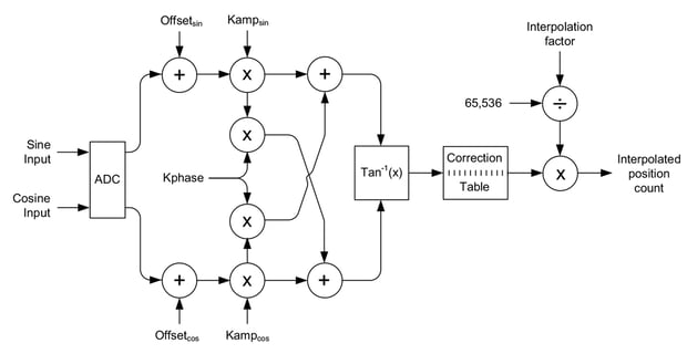
Figure 15: Sin/Cos Signal Correction Calculation Flow
For cases where the encoder output waveforms are not ideal, N-Series IONs provides an algorithmic correction scheme utilizing manually or automatically determined settable adjustment coefficients to correct the incoming signals. The correction scheme is shown in Figure 15 and the following table shows the settable correction coefficients:
| Parameter | Range | Default |
| Offsetsin Offsetcos |
-32,768 to +32,767 | 0 |
| Kampsin Kampcos |
0 to 32,767 | 16,384 |
| Kphase | -16,384 to 16,383 | 0 |
BiSS-C & SSI
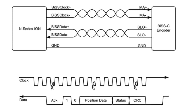
Figure 16: BiSS Encoder Format Interconnection Diagram and Serial Data Stream
BiSS-C (Bidirectional Serial/Synchronous interface) is a synchronous serial interface for acquiring position data from an encoder. It is a master/slave interface, with the N-Series ION functioning as the master and controlling the timing of position acquisition, and the encoder functioning as the slave. The signal interfacing scheme and serial data transfer format for typical BiSS-C encoders are shown in Figure 16 above.
The N-Series ION circuitry which supports BiSS-C encoders also supports SSI (Synchronous Serial Interface) encoders. To allow configuration of the BiSS-C interface for various encoders the following interface settings are available to the user:
| Parameter | Range | Bit Field |
| BiSS Enable (PIO register 0x106) | ||
| Enable/Disable | 0 – Disabled 1 – Enabled |
0 |
| BiSS Config (PIO register 0x100) | ||
| Position data format | 0 – Binary 1 – Gray code |
2 |
| BiSS-C or SSI encoder format | 0 – SSI 1 – BiSS-C |
3 |
| CRC word format | 0 – No CRC 1 – 60bit, (0x43) |
4:8 |
| BiSS Resolution (PIO register 0x102) | ||
| Position word size | 7-31 | 0:4 |
| BiSS Frequency (PIO register 0x104) | ||
| Clock frequency | 1-511 (10 MHz to 3.1 kHz) | 0:8 |
Appendix I - Configurations, Parameters, and Performance.
| Supported motor types | DC Brush, Brushless DC, Step motor |
| Profile modes | S-curve point-to-point - Position, velocity, acceleration, deceleration, jerk Trapezoidal point-to-point - Position, velocity, acceleration, deceleration |
| Velocity-contouring | Velocity, acceleration, deceleration Electronic gearing - gear ratio |
| Position | Scalable PID with velocity and acceleration feedforward, integration limit, offset bias, dual biquad filter, and settable derivative sampling time. Also supports dual encoder feedback. |
| Current loop | FOC (Field Oriented Control) with space-vector PWM, leg current sensing, scalable PI with integration limit and torque/current limit |
| Motion Control IC NVRAM | 4 KB |
| Motion Control IC trace RAM | 32 KB |
| Maximum number of simultaneous trace variables | 4 |
| Commutation rate | 19.53 kHz |
| Current loop rate | 19.53 kHz |
| PWM frequency | 20 kHz, 40 kHz, 80 kHz, 120 kHz (user selectable) |
| Servo cycle time range | 51.2 μseconds (19.53 kHz) to 1.114 seconds |
| Position range | -2,147,483,648 to +2,147,483,647 counts or steps |
| Velocity range | -32,768 to +32,767 counts or steps per cycle with a resolution of 1/65,536 counts or steps per cycle |
| Acceleration and deceleration ranges | 0 to +32,767 counts or steps per cycle2 with a resolution of 1/65,536 counts or steps per cycle2 |
| Jerk range 0 to ½ counts or steps per cycle3 with a resolution of 1/4,294,967,296 | Jerk range 0 to ½ counts or steps per cycle3 with a resolution of 1/4,294,967,296 counts or steps per cycle3 |
| Electronic gear ratio range | -32,768 to +32,767 with a resolution of 1/65,536 (negative and positive direction) |
| Position error tracking | Motion error window allows axis to be stopped upon exceeding programmable window Tracking window allows flag to be set if position error is within a programmable position window Axis settled function allows flag to be set if position error is within programmable position window for a programmable amount of time after trajectory motion is complete |
| Multi-axis synchronization | <1 μsecs difference between master and slave servo cycle |
| Current measurement resolution | 12 |
| Brushless DC commutation sources | Hall sensors, encoder |
| Microstepping resolution | Up to 256 microsteps per full step |
| Axis control signals | Enable, AxisIn, AxisOut, SynchIn, SynchOut, HostInterrupt, PosLim, NegLim, Home, FaultOut |
| Motor amplifier | Four quadrant MOSFET-based switching amplifier with individual leg current sensing |
| Current control options | Individual phase, FOC (Field Oriented Control), third leg floating |
| Drive safety functions | Over current detect, over temperature detect, over voltage detect, under voltage detect, I2t current foldback, Brake signal, 5V overcurrent detect |
| Brake modes | Passive braking, full disable |
| Shunt resistor control | Yes (for DC Brush and Brushless DC motors) |
| Host communications options | Serial, CAN, Ethernet, SPI (Serial Peripheral Interface) |
| Serial ports | Serial1, Serial2 (serial host interface unit only), Serial3 (all units) |
| Serial protocols supported | RS232 (Serial1, Serial2), RS422 (Serial1), RS485 half duplex (Serial1), RS485 full duplex (Serial1), UART (Serial3) |
| Serial port baud range | 1,200 to 921, 600 (Serial1, Serial2, Serial3) |
| CAN ports | HostCAN (CAN/SPI host interface unit only), ExpCAN (all units) |
| CAN protocols supported | CAN FD (HostCAN, ExpCAN) |
| CAN FD nominal baud rate | 10,000 to 1,000,000 |
| CAN FD data baud rate | 10,000 to 5,000,000 |
| SPI ports | HostSPI (CAN/SPI host interface unit only), ExpSPI (all units) |
| SPI clock range | 0.10 to 20.0 MHz |
| Expansion SPI clock frequency | 625 kHz, 1.25 MHz, 2.5 MHz, 5 MHz, 10 MHz, 20 MHz |
| Ethernet port | 100 Base-T Ethernet (Ethernet host interface unit only) |
| Ethernet protocols supported | TCP, UDP, DHCP |
| Encoder formats supported | Quadrature AB, pulse & direction, sin/cos, BiSS-C |
| Position capture signal sources | Index, home |
| Quadrature max rate | 40 Mcounts/sec |
| Pulse input max rate | 10 Mpulses/sec |
| Sin/Cos max frequency | 500 kHz |
| Sin/Cos interpolation factor range | 4 to 65,536 |
| Sin/Cos calibration settings | Sin analog offset, cos analog offset, Sin analog scale, Cos analog scale, Kphase, 32-entry derived angle correction table |
| C-Motion engine CPU speed | 428 MIPS |
| User program space NVRAM | 256 KB |
| User stack RAM | 256 KB |
| User scratch RAM | 64 KB |
| Max # of user tasks | 16 |
| High priority task response time | 5.0 μSec or less |
| Nominal task switch time | 1.0 mSec |
| Real time clock accuracy | +/-50 ppm |
| Powered-off battery draw | 3 μA typical |
| General purpose device NVRAM size | 128 KB |
| General purpose device RAM size | 64 KB |
| General purpose digital IOs | 8 bi-directional digital I/Os (4 push-pull, 4 open collector) |
| General purpose analog input | 1 channel differential +/-10V analog input |
| Analog input measurement resolution | 16 bits |
Appendix II – Drive Ratings, Maximum Ratings, and Environmental Ratings, Safety & Compliance
Low Power Units (P/Ns DD4x1x0056/02)
| Specifications* | DC Brush Motor | Brushless DC Motor | Step Motor |
| Nominal supply voltage | 12-56 VDC | 12-56 VDC | 12-56 VDC |
| Continuous phase current | 1.5 ADC | 1.5 Arms | 1.5 Arms |
| Peak current (per phase) | 3.8 A | 3.8 A | 3.8 A |
| Maximum continuous power | 84 W | 103 W | 119 W |
Medium Power Units (P/Ns DD4x1x0056/06)
| Specifications* | DC Brush Motor | Brushless DC Motor | Step Motor |
| Nominal supply voltage | 12-56 VDC | 12-56 VDC | 12-56 VDC |
| Continuous phase current | 7.1 ADC | 5.5 Arms | 5.0 Arms |
| Peak current (per phase) | 14.0 A | 14.0 A | 14.0 A |
| Maximum continuous power | 396 W | 379 W | 396 W |
High Power Units (P/Ns DD4x1x0056/18)
| Specifications* | DC Brush Motor | Brushless DC Motor | Step Motor |
| Nominal supply voltage | 12-56 VDC | 12-56 VDC | 12-56 VDC |
| Continuous phase current | 19.0 ADC | 14.8 Arms | 13.4 Arms |
| Peak current (per phase) | 33.0 A | 33.0 A | 33.0 A |
| Maximum continuous power | 1,064 W | 1,018 W | 1,064 W |
* Transformer isolated power supply, T < 40° C
A coldplate or a heatsink in an environment with sufficient airflow can be used to achieve the above drive ratings.
For temperature operation beyond the standard 0-40° C range above-listed ratings may change. Contact your PMD representative for additional information on extended temperature operation including higher temperature drive ratings.
Absolute Maximum Ratings
| Parameter | Rating |
| HV voltage range, low power units | 0 V to +60 V |
| HV voltage range, medium power units | 0 V to +60 V |
| HV voltage range, high power units | 0 V to +60 V |
| Serial signals: Srl1Rcv/RS485Rcv+, Srl1Rcv/RS485Rcv-voltage range | -15 V to +15 V |
| CAN signals: HostCAN+, HostCAN-, ExpCAN+, Exp-CAN- voltage range | -14 V to +14 V |
| SPI signals: HostSPIClock, HostSPIRcv, HostSPISelect voltage range | -0.5 V to 6.5 V |
| Digital IO1-4 | -0.5 V to 6.5 V |
| Digital IO5-8 | -0.5 V to 30 V |
| Misc. signals: Enable, Hall A, Hall B, Hall C, Home, PosLimit, NegLimit, AxisIn voltage range | -0.3V to 30V |
| FaultOut voltage range | -0.3V to 30V |
| 5V output current | 50 mA |
Environmental Ratings
| Specification | Value |
| Operating ambient temperature | 0 to 40 C |
| Maximum base plate temperature | 70 C |
| Storage temperature | -20 to 85 C |
| Reflow soldering temperature | 300 C (1.5mm for 10 seconds) |
| Humidity | 0 to 95%, non-condensing |
| Altitude | Up to 2,000 meters without derating |
| Contamination | Pollution Degree 2 |
Safety and Compliance
| Specification | Standard |
| CE | LVD: EN60204-1 EMC-D: EN61000-6-1, EN61000-6-3, EN55011 |
| Electrical safety | Designed to UL61800-5-1, UL508C, UL840 and EN60204-1 |
| Hazardous materials | RoHS compliant |
| Flammability | UL94-HB |
| Enclosure | IP20 |
Appendix III – Pin Quick Reference
Power Connector
| Pin | Name |
| 1 | HV Aux |
| 2 | HV |
| 3 | GND |
| 4 | Motor A |
| 5 | Motor B |
| 6 | Motor C |
| 7 | Motor D/Shunt |
Signal Connector – Serial Host Interface
| Pin | Name | Pin | Name |
| 1 | Srl2Xmt/RS485Xmt- | 2 | Srl1Xmt/RS485Xmt+ |
| 3 | Srl2Rcv/RS485Rcv- | 4 | Srl1Rcv/RS485Rcv+ |
| 5 | N.C. | 6 | N.C. |
| 7 | ExpCAN+ | 8 | ExpCAN- |
| 9 | RS485Sel/DigitalIO8 | 10 | GND |
| 11 | QuadA2+ | 12 | QuadA2- |
| 13 | QuadB2+ | 14 | QuadB2- |
| 15 | Index1+/BiSSClock+ | 16 | Index1-/BiSSClock- |
| 17 | Index2+/BiSSData+ | 18 | Index2-/BiSSData- |
| 19 | HallA | 20 | HallB |
| 21 | HallC | 22 | PosLim |
| 23 | NegLim | 24 | Home |
| 25 | Enable | 26 | FaultOut |
| 27 | Reset | 28 | Brake |
| 29 | 5V | 30 | GND |
| 31 | Srl3Xmt/DigitalIO1/ExpSPIXmt | 32 | Srl3Rcv/DigitalIO2/ExpSPIRcv |
| 33 | AxisIn/DigitalIO3/ExpSPIClock | 34 | SynchIn/DigitalIO4/ExpSPICS1 |
| 35 | AxisOut/DigitalIO5/ExpSPICS2 | 36 | HostInterrupt/DigitalIO6/ExpSPICS3 |
| 37 | SynchOut/DigitalIO7/ExpSPICS4/ ExpSPIStatus |
38 | GND |
| 39 | QuadB1+/Direction1+/Sin+ | 40 | QuadB1-/Direction1-/Sin- |
| 41 | QuadA1+/Pulse1+/Cos+/Index2Alt+ | 42 | QuadA1-/Pulse1-/Cos-/Index2Alt- |
| 43 | AnalogIn+ | 44 | AnalogIn- |
Signal Connector – CAN/SPI Host Interface
| Pin | Name | Pin | Name |
| 1 | HostSPIXmt | 2 | HostSPIClock |
| 3 | HostSPIRcv | 4 | HostSPISelect |
| 5 | HostCAN+ | 6 | HostCAN- |
| 7 | ExpCAN+ | 8 | ExpCAN- |
| 9 | HostSPIStatus/DigitalIO8 | 10 | GND |
| 11 | QuadA2+ | 12 | QuadA2- |
| 13 | QuadB2+ | 14 | QuadB2- |
| 15 | Index1+/BiSSClock+ | 16 | Index1-/BiSSClock- |
| 17 | Index2+/BiSSData+ | 18 | Index2-/BiSSData- |
| 19 | HallA | 20 | HallB |
| 21 | HallC | 22 | PosLim |
| 23 | NegLim | 24 | Home |
| 25 | Enable | 26 | FaultOut |
| 27 | Reset | 28 | Brake |
| 29 | 5V | 30 | GND |
| 31 | Srl3Xmt/DigitalIO1/ExpSPIXmt | 32 | Srl3Rcv/DigitalIO2/ExpSPIRcv |
| 33 | AxisIn/DigitalIO3/ExpSPIClock | 34 | SynchIn/DigitalIO4/ExpSPICS1 |
| 35 | AxisOut/DigitalIO5/ExpSPICS2 | 36 | HostInterrupt/DigitalIO6/ExpSPICS3 |
| 37 | SynchOut/DigitalIO7/ExpSPICS4/ ExpSPIStatus |
38 | GND |
| 39 | QuadB1+/Direction1+/Sin+ | 40 | QuadB1-/Direction1-/Sin- |
| 41 | QuadA1+/Pulse1+/Cos+/Index2Alt+ | 42 | QuadA1-/Pulse1-/Cos-/Index2Alt- |
| 43 | AnalogIn+ | 44 | AnalogIn- |
Signal Connector – Ethernet Host Interface
| Pin | Name | Pin | Name |
| 1 | EthernetTx+ | 2 | EthernetTx- |
| 3 | EthernetRx+ | 4 | EthernetRx- |
| 5 | TapTx | 6 | TapRx |
| 7 | ExpCAN+ | 8 | ExpCAN- |
| 9 | DigitalIO8 | 10 | GND |
| 11 | QuadA2+/Pulse2+ | 12 | QuadA2-/Pulse2- |
| 13 | QuadB2+/Direction2+ | 14 | QuadB2-/Direction2- |
| 15 | Index1+/BiSSClock+ | 16 | Index1-/BiSSClock- |
| 17 | Index2+/BiSSData+ | 18 | Index2-/BiSSData- |
| 19 | HallA | 20 | HallB |
| 21 | HallC | 22 | PosLim |
| 23 | NegLim | 24 | Home |
| 25 | Enable | 26 | FaultOut |
| 27 | Reset | 28 | Brake |
| 29 | 5V | 30 | GND |
| 31 | Srl3Xmt/DigitalIO1/ExpSPIXmt | 32 | Srl3Rcv/DigitalIO2/ExpSPIRcv |
| 33 | AxisIn/DigitalIO3/ExpSPIClock | 34 | SynchIn/DigitalIO4/ExpSPICS1 |
| 35 | AxisOut/DigitalIO5/ExpSPICS2 | 36 | HostInterrupt/DigitalIO6/ExpSPICS3 |
| 37 | SynchOut/DigitalIO7/ExpSPICS4/ ExpSPIStatus/EthLinkLED |
38 | GND |
| 39 | QuadB1+/Direction1+/Sin+ | 40 | QuadB1-/Direction1-/Sin- |
| 41 | QuadA1+/Pulse1+/Cos+/Index2Alt+ | 42 | QuadA1-/Pulse1-/Cos-/Index2Alt- |
| 43 | AnalogIn+ | 44 | AnalogIn- |
Appendix IV – Mechanical Dimensions & Mounting Information
Physical Dimensions
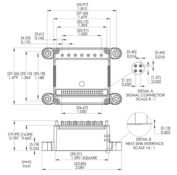
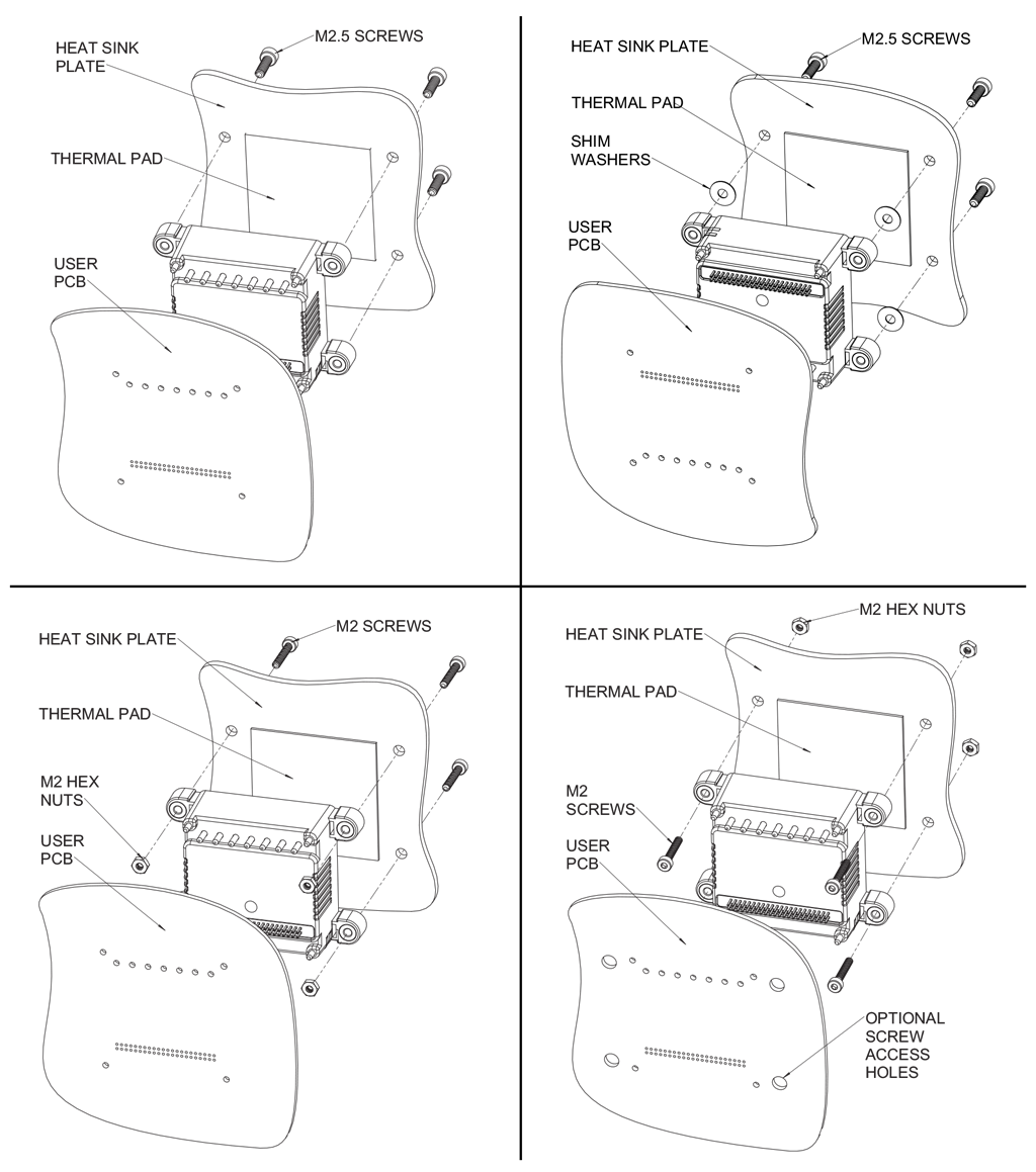
Attachment to the Heat Sink
Appendix V – Developer Kit Part Numbers
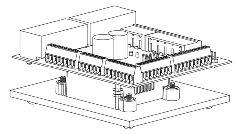
The ION/CME N-Series Digital Drive Developer Kits are integrated board/software packages that serve as a mechanical, electrical, and software design tool for prototyping and building systems with N-Series ION Drives.
The core of each developer kit is an interconnect board that provides convenient connections to your PC, the motor hardware, and other peripherals that will be used in your application.
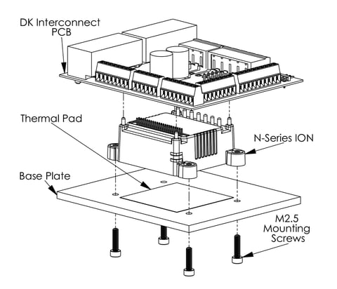
As shown in the Figure above the N-Series ION is mounted in between a metallic heat sink base (which also serves the purpose of providing a footing for bench-top use) and the DK interconnect board which provides the connectors.
Alternatively, you can remove the metallic heat sink base and mount the N-Series ION with attached DK interconnect board directly on your machine hardware. For exact dimensions of the N-Series ION refer to Appendix IV.
Pre-Assembled Developer Kits
| DK P/N | ION P/N INSTALLED | HOST INTERFACE | POWER LEVEL |
| DK481S0056/02 | DD481S0056/02 | Serial | Low |
| DK481S0056/06 | DD481S0056/06 | Serial | Medium |
| DK481S0056/18 | DD481S0056/18 | Serial | High |
| DK481C0056/02 | DD481C0056/02 | CAN/SPI | Low |
| DK481C0056/06 | DD481C0056/06 | CAN/SPI | Medium |
| DK481C0056/18 | DD481C0056/18 | CAN/SPI | High |
| DK481D0056/02 | DD481D0056/02 | Ethernet | Low |
| DK481D0056/06 | DD481D0056/06 | Ethernet | Medium |
| DK481D0056/18 | DD481D0056/18 | Ethernet | High |
Developer Kit Part Numbers (Non Pre-assembled)
There may be occasions where it is preferable for the user to assemble an N-Series ION developer kit themselves. The main advantage of this is that it allows developer kit setups to be created with N-Series IONs other than the multi-motor type.
To facilitate this three non pre-assembled component developer kits are available.
| DK P/N | HOST INTERFACE | COMMENTS |
| DK4X1S | Serial | Supports all serial host interface N-Series ION units |
| DK4X1C | CAN/SPI | Supports all CAN/SPI host interface N-Series ION units |
| DK4X1D | Ethernet | Supports all Ethernet host interface N-Series ION units |
Each of these component-only DKs contain a DK interconnect PCB, a metallic base plate, and various mounting hardware such as screws and a thermal pad to allow the user to assemble a complete DK setup. Note that these DKs P/Ns do not include the N-Series ION unit itself. The N-Series ION must be ordered separately.
For instructions on how to assemble a developer kit setup from a component-only DK, refer to Section 3.5 of the ION/CME N-Series Digital Drive Developer Kit User Manual.
Additional Resources
- Full Product Info
- ION/CME N-Series Digital Drives Datasheet
- ION/CME N-Series Digital Drives User Manual
- ION/CME N-Series Digital Drives Developer Kits
- PMD Resource Center