 The ION®/CME 500 Digital Drives are a family of single-axis motion controllers with integrated power electronics and network communications. Various models are available to drive DC Brush, Brushless DC, and step motors with up to 500 watts of power output.
ION 500 digital drives are based on PMD’s Magellan Motion Control IC technology and perform profile generation, encoder position feedback, position servo compensation, step motor stall detection, Brushless DC motor commutation, microstep generation, digital current/torque control, and more. Network communications options include Ethernet, RS485, and RS232.
These products have integrated, high-power drive stages which fully protect from overcurrent, undervoltage, overvoltage, overtemperature, and short-circuit faults. In addition to extensive motion I/O capability, ION/CMEs feature auxiliary encoder input and dedicated Enable input and Fault output safety interlocks. ION/CME 500 Digital Drives provide an internal C-Motion Engine allowing user code to be downloaded into the ION for full standalone operation.
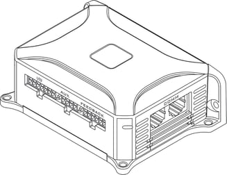
ION/CME 500s are packaged in a rugged plastic and metal module measuring 4.267” x 3.03" x 1.48" (108 mm x 77 mm x 37 mm). They utilize a 3-pin Power Connector, 5-pin Motor Connector, 12-pin Feedback Connector, 8-pin Auxiliary Connector, and 20-pin Indexer Connector.
Additional members of the ION Digital Drive family include ION 3000, a high voltage 3,000W drive and N-Series ION, an ultra-compact PCB-mounted drives with up to 1,000W output and additional features such as BiSS-C & sin/cos encoder support, CANFD network support, full user programmability, 16-bit analog input, field oriented control, and auto-tuning.
Available Configurations
There are three different members of the ION/CME 500 family, each representing a different motor type. The chart below shows a complete P/N diagram for all ION products including ION/CME 500, ION 3000, and N-Series ION products.
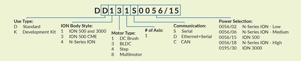
The following table shows the available ION/CME 500 part numbers:
|
Part Number
|
Motor Type
|
Communicaton Ports
|
|
Brushless DC
|
Ethernet/Serial
|
|
|
DC Brush
|
Ethernet/Serial
|
|
|
Step Motor
|
Ethernet/Serial
|
Developer Kits
Although ION/CME units come fully assembled and ready for operation, a developer kit is available which provides useful cable sets for quick start up.
|
Part Number
|
Description
|
|
ION/CME 500 Developer Kit, Serial/Ethernet
(Cable set only, ION unit not included) |
ION/CME 500 Feature List
- Host communications over Ethernet, RS232, or RS485
- Ability to download and execute user application code in the ION
- 256 KB of programmable user code space
- Code execution rate up to 96 MIPS (million instructions per second)
- Advanced C-Motion Engine development tools
- Trajectory generation, including trapezoidal and S-curve point-to-point profiling, velocity contouring, and electronic gearing modes
- Advanced PID position loop with integration limit, derivative sample time, velocity and acceleration feedforward, output bias, dual biquad filters, and support for dual encoder feedback
- Indexer connector providing additional digital I/O and 16-bit analog input
- Two encoder input channels capable of up to 10 Mcounts per second
- Sinusoidal and six-step (Hall) Brushless DC commutation modes
- Microstepping outputs with up to 256 microsteps per step
- Digital current loop with choice of standard A/B or Field Oriented Control (FOC) for both Brushless DC and step motors
- Single phase current loop for DC Brush motors
- Pulse and direction input
- High-efficiency MOSFET power stages with versions for single-phase brush DC motors, two-phase step motors, and three-phase Brushless DC motors
- I2t current foldback limiting
- Selectable 20 kHz and 40 kHz PWM frequencies to support a broad range of motor inductance
- Overcurrent, short circuit, overvoltage, undervoltage, and overtemperature protection
- Single supply operation. An onboard DC/DC converter supplies all internal circuitry and also provides 5V for encoders and other external I/O
- Enable input and Fault output safety interlock
- Differential or single-ended encoder input buffers for all encoder channels
- Signal conditioning buffers and analog filters on all I/O signals
Internal Block Diagram
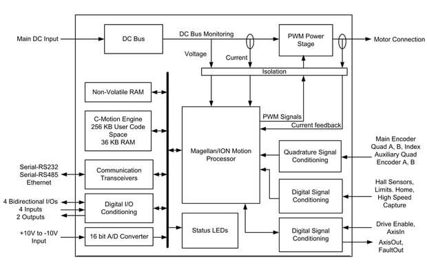
Figure 1: ION/CME 500 Internal Block Diagram
ION/CME 500 Functions
ION/CME 500 functions can be broken down into the following groups:
Magellan IC Functions - These are functions which reside in the Magellan Motion Control IC. Included are profile generation, PID position loop closure, breakpoint processing, current control, PWM signal generation, field oriented control, and much more.
Encoder Functions - These are the functions related to quadrature encoder and pulse & direction input signal processing.
Motion Peripheral Functions - These are the functions directly related to Magellan IC axis signals such as Enable, FaultOut, Home, limit switch inputs, Hall inputs, and AxisIn & AxisOut.
I/O Functions - These are digital and analog input and output functions. There are 8 general purpose bi-directional digital channels, and there is one general purpose +/- 10V analog input channel.
Communications Functions - The ION/CME provide sophisticated communication facilities consisting of 10/100 base-T Ethernet, RS232, and RS485 interfaces.
Power Stage Functions - The on-board amplifier accepts motor output commands from the Magellan Motion Control IC and provides high-performance amplification and current control for step, DC Brush, or Brushless DC motors.
Drive Safety Functions - ION provides numerous safety and DC bus management functions including detection and protection from over current, over temperature, over/under voltage, and more.
C-Motion Engine Functions - The C-Motion Engine is a self-contained, high-performance code execution unit that allows C-Motion code to be downloaded and executed on the ION/CME 500. It can communicate with various resources on the board including the Magellan Motion Control IC, the drive’s serial and Ethernet ports, NVRAM, and other resources.
General Drive Functions - These are functions associated with general drive facilities including non-volatile RAM, LED control, and other functions.
Typical Applications
Position, Velocity, and Torque Control of Brushless DC and DC Brush Motors
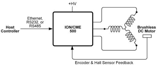
Figure 2: Position, Velocity, and Torque Control of Brushless DC and DC Brush Motors
In this application the ION/CME 500 receives commands from a host via an Ethernet, RS232 or RS485 network and provides high performance profile generation and position, velocity, or torque control of DC Brush or Brushless DC motors via a PID (Proportional, Integral, Derivative) or PI servo control loop. Quadrature encoder or Hall sensor feedback is used for feedback. For Brushless DC motors Hall sensors normally provide commutation feedback. If encoder signals are available however Halls are not required as long as the motor can move freely during startup. Additional signals provided include a home switch, directional limit switches, and general purpose digital and analog I/O.
In the diagram above a Brushless DC motor is shown but similar control can be provided for DC Brush motors.
Additional Hardware Needed: The ION/CME 500 is powered directly via a single +HV voltage and provides all electrical functionality for this application. The only additional hardware needed are cables to connect the host network, ION/CME’s DC power input, and motor and signal connections to the corresponding external motion peripherals.
Pulse & Direction Control of Step Motors
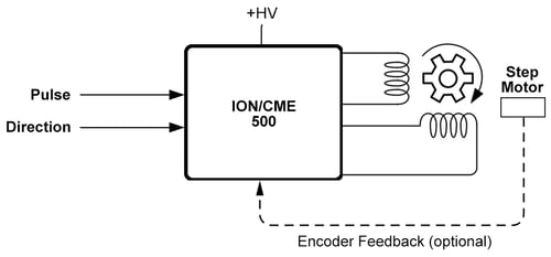
Figure 3: Pulse & Direction Control of Step Motors
In this application a PLC (programmable logic controller) or motion control board provides pulse and direction commands to the ION/CME 500 which controls a two-phase step motor. Encoder feedback for stall detection is supported but optional.
Additional Hardware Needed: The ION/CME 500 is powered directly via a single +HV voltage and provides all electrical functionality for this application. The only additional hardware needed are cables to connect the pulse & direction input DC power input, motor coil connections, and signal connections to the motion peripherals such as the encoder.
Pulse & Direction Control of Brushless DC and DC Brush Motors
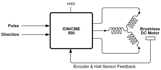
Figure 4: Pulse & Direction Control of Brushless DC and DC Brush Motors
In this application a PLC (programmable logic controller) or motion control board provides pulse and direction commands to the ION/CME 500 which controls a servo motor such as a DC Brush or Brushless DC motor. The incoming pulse & direction signals provide the position command which is used together with a PID (Proportional, Integral, Derivative) loop to provide position control. Quadrature encoder or Hall sensor feedback is used for feedback. For Brushless DC motors Hall sensors normally provide commutation feedback. If encoder signals are available however Halls are not required as long as the motor can move freely during startup.
Additional Hardware Needed: The ION/CME 500 is powered directly via a single +HV voltage and provides all electrical functionality for this application. The only additional hardware needed are cables to connect the pulse & direction input, DC power input, motor coil connections, and signal connections to the motion peripherals such as the encoder.
Closed Loop Operation of Step Motors
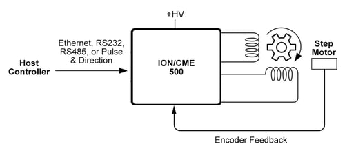
Figure 5: Closed Loop Operation of Step Motors
In this configuration, the ION/CME 500 executes closed loop control (also called servo stepper operation) of a step motor. In this control mode the step motor is operated as a commutated two-phase servo motor. Relative to traditional microstepping step motor operation closed loop control provides smoother motion, less noise, higher acceleration, and eliminates the problem of lost steps.
Quadrature encoder input is required for closed loop step motor operation. Other than the approach toward step motor control, the features provided with this configuration are the same as for the previously shown configurations.
Additional Hardware Needed: The ION/CME 500 is powered directly via a single +HV voltage and provides all electrical functionality for this application. The only additional hardware needed are cables to connect the pulse & direction input, DC power input, motor coil connections, and signal connections to the motion peripherals such as the encoder.
Force or Pressure Control With Brushless DC or DC Brush Motors
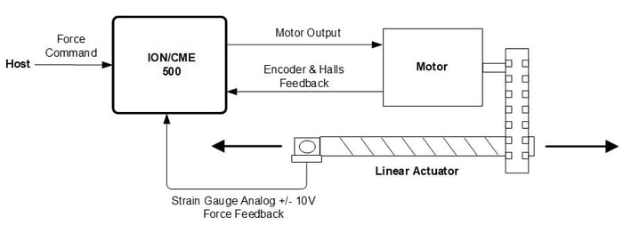
Figure 6: Force or Pressure Control
In this application the ION/CME 500 receives host commands from an external network or internally from downloaded user code representing a desired force or pressure. An external force or pressure sensor provides an analog feedback signal which is input directly to the ION/CME 500 and used to create a corrective motion command which is then output by the ION/CME 500 to achieve precise force or pressure control.
Note that in the diagram above a linear actuator with a strain gauge is shown however pressure control can similarly be achieved using a pressure sensor location inside the pressure chamber to be regulated, with the motor being controlled driving a pump.
Additional Hardware Needed: ION/CME 500s are powered directly via a single +HV voltage and provide all electrical functionality for this application. The only additional hardware needed are cables to connect the host, DC power input, motor coil connections, signal connections to the motion peripherals such as the encoder, and the strain gauge force measurement signal.
CAM Profile Control of Brushless DC, DC Brush, or Step Motors
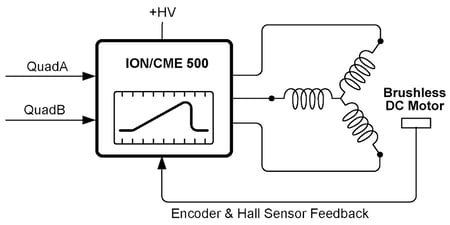
Figure 7: CAM Profile Control
In this application the ION/CME 500 inputs a quadrature position data stream from an external encoder via its Auxiliary encoder input and uses it as the master rate command for execution of an internally stored cam or electronic gear profile. Prior to profile operation the cam profile shape is stored by the user in the ION unit. Execution of camming functions and of other complex shapes is enabled via PMD’s User Defined Profile Mode.
The above diagram shows a Brushless DC motor but similar control can be provided for DC Brush and step motors.
Additional Hardware Needed: ION/CME 500s are powered directly via a single +HV voltage and provide all electrical functionality for this application. The only additional hardware needed are cables to connect the master encoder command input, DC power input, motor coil connections, and signal connections to the motion peripherals such as the motor position encoder.
Network Connected Drive
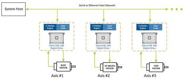
Figure 8: Network Connected Drive
In this application, one or more ION/CME 500s connect directly to an RS485 or Ethernet network and provide control of Brushless DC, DC Brush, or step motors. Commands are sent by the host to each ION/CME 500 to accomplish the overall machine function. In addition to ION/CME 500s, other types of PMD products such as N-Series IONs or Prodigy boards, along with non-PMD network-attached devices may be included in the network.
In this configuration downloading user code to the ION/CME 500 is optional. Attached IONs may execute downloaded user code or may operate by direct command from the host.
Host-Connected Machine Controller
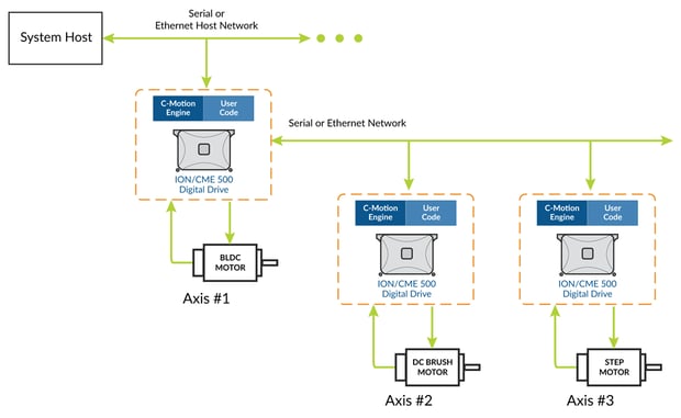
Figure 9: Host-Connected Machine Controller
In this application one ION/CME 500 (axis #1) interfaces directly to a Serial or Ethernet network, and this same ION unit directly controls one or more additional ION/CME 500s connected via a RS485 or Ethernet ‘sub-network’. The sub-network must be of a different type than the host-connected network. For example if the host network is Ethernet the sub-network is RS485 and vice versa. User-written application code is downloaded into the host-connected ION's C-Motion Engine. This code processes commands from the host network and generates motion sequences for its own motor axis and the sub-network-attached motor axes to accomplish the desired machine behavior.
Standalone Controller With User Interface
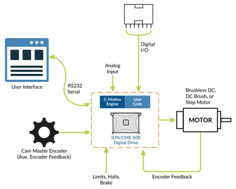
Figure 10: Standalone Controller With User Interface
In this application an ION/CME 500 functions as a complete standalone controller. The ION connects via its RS232 port to a user interface module which allows an operator to configure the control function. Digital I/Os from a PLC select various user-defined functions to execute. Standalone function of the ION/CME 500 is achieved via user-written code that is downloaded into, and executed directly, by the ION unit. This code is written in PMD’s C-Motion language which is based on standard C/C++.
Although a user interface module is shown in the diagram above, the ION/CME 500’s Ethernet and serial connection channels can be used to communicate to a wide variety of components, computers, or machines. How these communication channels are utilized is determined by the user-written C-Motion application code that is downloaded into the ION/CME 500.
ION/CME 500 Key Product Features
Advanced Instruction Set
All IONS utilize a PMD Magellan motion control IC for advanced motion control functions.
The Magellan instruction set is flexible and powerful. The following very simple example, which sets up and executes a trapezoidal profile, illustrates just a small part of the overall command set. In addition, this small sequence shows the look and feel of C-Motion, PMD’s C-language callable motion interface that handles communications to and from all machine controller board resources.
|
PMDSetProfileMode(&hAxis1, PMDProfileTrapezoidal);
|
// set profile mode to trapezoidal for axis 1
|
|
PMDSetPosition(&hAxis1, 12345);
|
// load a destination position for axis 1
|
|
PMDSetVelocity(&hAxis1, 223344);
|
// load a velocity for axis 1
|
|
PMDSetAcceleration(&hAxis1, 1000);
|
// load an acceleration for axis 1
|
|
PMDSetDeceleration(&hAxis1, 2000);
|
// load a deceleration for axis 1
|
|
PMDUpdate(&hAxis1);
|
// initiate the move
|
hAxis1 is a handle to a structure known as a PMDAxisHandle. There are several different C-Motion structures, and in general, they are used to make accessing the ION/CME 500 simpler and more flexible. In particular, by developing code with C-Motion, it is very easy to change the physical location of a PMD axis without any changes to the developed C-Motion code sequences. This is called axis virtualization and is a powerful feature of the C-Motion/Magellan IC system.
Seven-Segment S-Curve Profiling
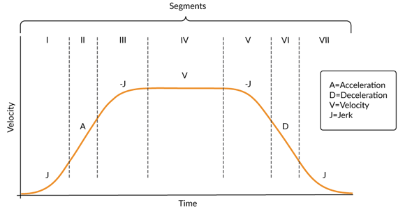
Figure 11: S-curve Profile
While trapezoidal profiles are very common in motion control, the S-curve profile is actually the workhorse for point to point motion because of its greater ability to control the amount of vibrational energy injected into the load. S-curve profiles add a limit to the rate of change of acceleration to the trapezoidal profile. This parameter, known as jerk, specifies the maximum change in acceleration per unit time.
Figure 11 shows a typical S-curve profile. In Segment I, the S-curve profile drives the axis at the specified jerk (J) until the maximum acceleration (A) is reached. The axis continues to accelerate linearly (jerk = 0) through Segment II. The profile then applies the negative value of the jerk to reduce acceleration to 0 during Segment III. The axis is now at maximum velocity (V), at which it continues through Segment IV. The profile will then decelerate in a manner similar to the acceleration stage, using the jerk value first to reach the maximum deceleration (D) and then to bring the axis to a halt at the destination.
Servo Tracking Window
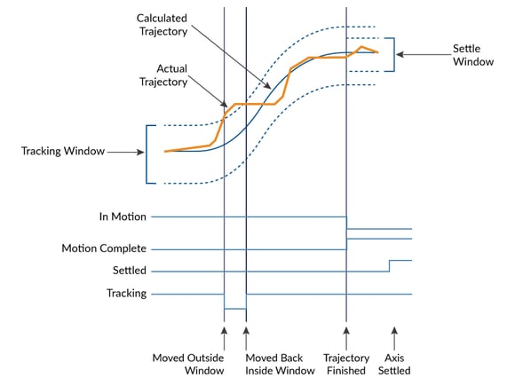
Figure 12: Servo Performance Monitoring
The ION/CME’s onboard Magellan Motion Control IC provides a programmable tracking window to monitor servo performance. To initiate this feature the user sets a programmable position error limit within which the axis must remain. Should the axis move outside of the tracking window the Magellan IC can be programmed to report this automatically via hardware signal.
The tracking window is particularly useful for external processes that rely on the motor’s correct tracking of the desired trajectory within a specific range. The tracking window may also be used as an early warning for performance problems that do not yet qualify as a motion error.
High Efficiency Digital Switching Motor Amplifier Control
The ION’s Magellan IC provides control of an on-PCB digital power stage with PWM (Pulse Width Modulation) control. A slightly different configuration is used for each motor type:
- DC Brush motors are driven with an H-Bridge consisting of 4 switches.
- Brushless DC motors are driven with a 3-phase bridge consisting of 6 switches.
- Step motors are driven with two H-Bridges, one for each phase, for a total of 8 switches.
The use of 3-phase and H-Bridge topologies provides full 4-quadrant operation.
IONs use an advanced PWM switching scheme that minimizes the ripple current on the motor windings while maximizing the current loop performance. The PWM frequency is selectable between 20 kHz and 40 kHz to cover a range of motor inductance. The fundamental frequency of the ripple current is twice the PWM frequency and well out of the audible range in all cases.
A representative diagram of the switch and current sense configuration is shown in Figure 13. The diagram shown is for Brushless DC motors, the configuration will be somewhat different for DC Brush and step motors.
In addition to highly efficient and powerful motor drive capacity IONs provide several important amplifier and DC voltage related safety features including over voltage, under voltage, overcurrent, over temperature, and I2T control for precise control of heating in the actuator and motor being driven.
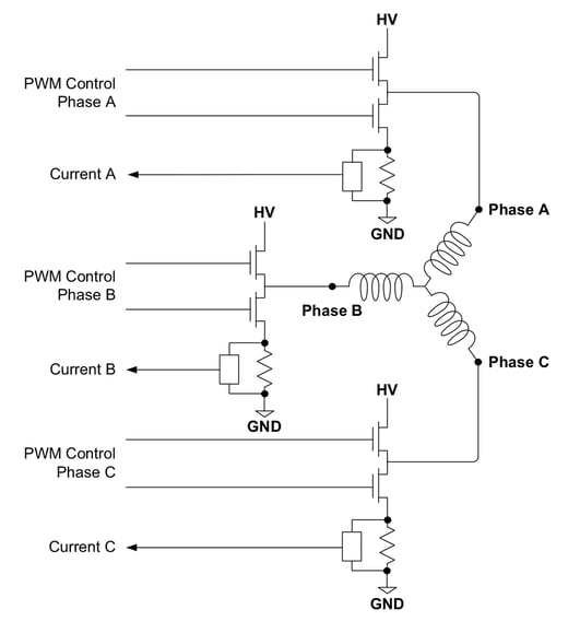
Figure 13: Brushless DC Motor Bridge Configuration
C-Motion Engine
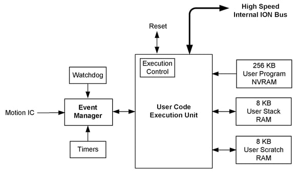
Figure 14: C-Motion Engine Internal Block Diagram
The C-Motion Engine (CME) allows user-written code to be downloaded and executed on the ION/CME 500. The C-Motion Engine is a powerful and flexible engine that can be used to:
- Operate ION/CME 500s in a standalone mode
- Offload time-critical code from the host to the ION unit
- Communicate via serial or Ethernet with a cell controller or other host controller
- Communicate to ION/CME 500, N-Series ION, or PMD Prodigy Motion Boards, or control system peripherals
- Lower system cost by combining functions that would otherwise reside in a separate board or microprocessor.
The CME is connected to other internal ION/CME 500 resources via a high-speed bus, allowing it to access the Magellan IC, the host communication ports, the LEDs, the device default NVRAM, and other internal resources.
Creating, compiling, downloading, and verifying a user C-Motion application on an ION/CME 500 is accomplished with the C-Motion Engine development system. The outcome of such a development sequence is a downloadable .bin code image that contains the user application code to be executed by the C-Motion Engine on the ION.
Downloaded user code executes on the CME at a rate as high as 96 MIPS, although within the code execution unit there is also an internal real-time operating system (RTOS) that utilizes some of these code execution resources to provide functions such as memory management.
Network Communications
ION/CME 500s provide three host communication interfaces: RS232, RS485, and Ethernet.
RS232, RS485
ION/CME 500s provide asynchronous serial communications in both RS232 and RS485 format.
In RS232 mode two serial ports are supported, referred to as Serial1 and Serial2. Serial1 serves as the host serial interface for the ION unit, while Serial2 serves as an extra general purpose RS232 port. While some applications will not need to use two serial ports, the second port may be useful during C-Motion application code debugging, or to communicate with various serial devices connected to the ION unit.
Settings & default values for Serial1 and Serial2:
|
Parameter
|
Range
|
Serial 1 Default
|
Serial 2 Default
|
|
Baud Rate
|
1,200 to 921,600
|
57,600
|
115,200
|
|
Parity
|
none, even, odd
|
none
|
none
|
|
Data Bits
|
5, 6, 7, 8
|
8
|
8
|
|
Stop Bits
|
1, 2
|
1
|
1
|
Ethernet
ION/CME 500s provide 10/100 Base-T Ethernet communications. Two different Ethernet protocols are supported; TCP (Transmission Control Protocol) and UDP (User Datagram Protocol). TCP is used for primary Ethernet communications to the ION unit, while UDP is typically used for non-critical applications such as data logging, or for the Pro-Motion console window.
|
Parameter
|
Range
|
Default
|
|
IPaddress
|
0.0.0.0 – 255.255.255.255
|
192.168.2.2
|
|
Netmask
|
0.0.0.0 – 255.255.255.255
|
255.255.255.0
|
|
Gateway
|
0.0.0.0 – 255.255.255.255
|
0.0.0.0
|
|
PRPListenTCPPort
|
0 – 65,535
|
40100
|
Appendix I - ION/CME Drive Ratings
|
Specification
|
DC Brush
|
Brushless DC
|
Step
|
|
Nominal supply voltage
|
48 VDC
|
48 VDC
|
48 VDC
|
|
Supply voltage range transformer isolated power supply
|
12–56 VDC
|
12–56 VDC
|
12–56 VDC
|
|
Output current (per phase)
• Continuous, DIN rail mount, w/heat sink, free air @ 25°C • Continuous, coldplate mount, Tbp*<50°C • Peak (2 sec) |
• 6 ADC • 9.8 ADC • 21.2 ADC |
• 6 Arms (8.5 ADC) • 8 Arms (11.3 ADC) • 15 Arms (21.2 ADC) |
• 5 Arms (7.1 ADC) • 5 Arms (7.1 ADC) • 15 Arms (21.2 ADC |
|
Maximum continuous output power
• Coldplate mount, Tbp*<50°C |
• 450 W |
• 500 W |
• 500 W |
*Tbp = Temperature of base plate
Appendix II - ION/CME Controller Performance
|
Supported motor type
|
DC Brush, Brushless DC, Step motor
|
|
|
Communications options
|
Ethernet, RS232/485, CANbus
|
|
|
Profile modes
|
S-curve point-to-point
|
Position, velocity, acceleration, deceleration, jerk parameters
|
|
|
Trapezoidal point-to-point
|
Position, velocity, acceleration, deceleration
|
|
Velocity-contouring
|
Velocity, acceleration, and deceleration
|
|
|
Electronic gear
|
Using auxiliary encoder
|
|
|
Position loop filter parameters
|
Scalable PID with Velocity and Acceleration feedforward, integration limit, offset bias, dual biquad filter, and settable derivative sampling time. Also supports dual encoder feedback.
|
|
|
Position error tracking
|
Motion error window
|
Allows axis to be stopped upon exceeding programmable window
|
|
|
Tracking window
|
Allows flag to be set if axis exceeds a programmable position window
|
|
Configurable loop modes
|
DC brush and Brushless DC motor versions
|
Position, torque/current and voltage
|
|
|
Step motor version
|
Open loop with stall detection, current, and voltage
|
|
Digital current loop
|
Filter parameters
|
Scalable PI with integration limit and torque/current limit
|
|
|
Configuration
|
Standard phase A/B control or FOC with state-vector PWM (user selectable)
|
|
Current feedback scaling
|
100% full scale equals 21.2A
|
|
|
Current foldback
|
DC brush and Brushless DC motor versions
|
Programmable I2t peak limiting
|
|
Brushless DC commutation modes
|
Sinusoidal and 6-step (Hall) commutation
|
|
|
Microstepping resolution
|
Up to 256 microsteps per step
|
|
|
Maximum encoder rate
|
10 Mcounts per second
|
|
|
PWM resolution
|
20 or 40 kHz (user selectable)
|
|
|
Loop rates
|
Commutation & current loop
|
51.2 μsec
|
|
|
Position loop & trajectory generator
|
102.4 μsec to 1.67 sec, selectable in multiples of 51.2 μsec from n = 2 to 215-1
|
Appendix III - ION/CME Electrical
|
AuxV input voltage range
|
12–56VDC
|
|
|
AuxV maximum current
|
0.5A
|
|
|
IO_5V supply output
|
5V ±2%, 150 mA (total max.), short circuit protected
|
|
|
Differential/single-ended encoder inputs
|
Signals
|
Main encoder (A+, A-, B+, B-, Index+, Index-)
Auxiliary encoder (A+, A-, B+, B-) |
|
|
Voltage range
|
0–5 VDC
|
|
Logic threshold
|
RS422 compatible
|
|
|
Maximum frequency
|
2.5 MHz
|
|
|
Phasing
|
A leads B by 90°±20°. Index low must align with the A low and B low states and be low for less than 540° total
|
|
|
Digital inputs
|
Signals
|
Hall A, Hall B, Hall C, Home, +Limit, -Limit, AxisIn, High-speed Capture, /Enable
|
|
|
Voltage range
|
0–24VDC
|
|
Logic threshold
|
TTL compatible
|
|
|
Digital outputs
|
Signal
|
AxisOut, FaultOut
|
|
|
Voltage range
|
0–24VDC
|
|
Output current
|
4 mA source, 100mA sink, short circuit protected to 30V
|
|
|
General purpose digital inputs
|
Available Inputs
|
4
|
|
|
Signals
|
DigitalIn1-4
|
|
Digital Input Type
|
Single Ended with internal 4.7Kohms pull up to 5V
|
|
|
Low Pass Filter Frequency
|
6 KHz
|
|
|
Logic type
|
TTL
|
|
|
Input voltage range
|
0–24VDC
|
|
|
Overvoltage Protection
|
<30V
|
|
|
General purpose digital outputs
|
Available Outputs
|
2
|
|
|
Signals
|
DigitalOut1-2
|
|
Digital Output Type
|
Open collector with internal 1k pullup to 5V
|
|
|
Maximum Sink Current
|
100mA
|
|
|
Overvoltage Protection
|
<30V
|
|
|
General purpose bidirectional digital Input/output
|
Available Inputs
|
4
|
|
|
Signals
|
DigitalIO5-8
|
|
Digital Input Type
|
Single Ended TTL with internal 4.7Kohms pull up to 5V
|
|
|
Digital Output Type
|
Open collector with internal 4.7k pull-up to 5V
|
|
|
Low Pass Filter Frequency
|
6 KHz
|
|
|
Maximum Sink Current
|
100mA
|
|
|
Overvoltage Protection
|
<30V
|
|
|
Analog input characteristics
|
Available Input
|
1
|
|
|
Signals
|
AnalogIn+, AnalogIn-
|
|
Input Signal Voltage Range
|
-10 to +10V
|
|
|
Resolution
|
16 Bits
|
|
|
Maximum Recommended Input Signal Frequency
|
2 KHz
|
|
|
Throughput
|
40 kSPS
|
|
|
Integral Non Linearity Error, Typical
|
+1 LSB
|
|
|
Integral Non Linearity Error, Maximum
|
+3 LSB
|
|
|
Overvoltage Protection
|
-35 to +40V
|
|
|
Common-Mode Range
|
-10 to +25V
|
|
|
Typical Differential Impedance
|
108 Kohms
|
|
|
Common Mode Rejection Ratio, Minimum
|
80 dB
|
|
|
RS232/485 communications
|
Baud Rates
|
1200, 2400, 9600, 19.2k, 57.6k, 115k, 230k, 460k
Default baud rate is 57.6k 460k support for RS485 only |
|
|
Isolation
|
None
|
|
Termination
|
None
|
|
|
Ethernet communications
|
Compatibility
|
100BASE-TX, 10BASE-T
|
|
Available Memory
|
Trace memory size
|
1,536 bytes or 384 samples
|
|
|
CME user code space (NVRAM)
|
256 KB
|
|
CME data RAM space
|
8 KB
|
|
|
CME user code stack space
|
8 KB
|
|
Appendix IV - ION/CME Connectors and Pinouts
High Power Connectors
|
Connector: Power |
Pin
|
Signal
|
|
1
|
+HV
|
|
|
2
|
AuxV
|
|
|
3
|
Pwr_Gnd
|
|
Connector: Motor |
Pin
|
Signal
|
|
1
|
Motor+, Motor A, Motor A+
|
|
|
2
|
Motor B, Motor AWire
|
|
|
3
|
Motor-, Motor C, Motor B+
|
|
|
4
|
Motor B-
|
|
|
5
|
Case/Shield
|
Signal Connectors
|
Connector: Feedback |
Pin
|
Signal
|
|
1
|
Shield
|
|
|
2
|
IO_Gnd
|
|
|
3
|
IO_5V
|
|
|
4
|
Hall A
|
|
|
5
|
Hall B
|
|
|
6
|
Hall C
|
|
|
7
|
Quad A+
|
|
|
8
|
Quad A-
|
|
|
9
|
Quad B+
|
|
|
10
|
Quad B-
|
|
|
11
|
Index+
|
|
|
12
|
Index
|
|
Connector: Auxiliary |
Pin
|
Signal
|
|
1
|
Shield
|
|
|
2
|
IO_Gnd
|
|
|
3
|
IO_5V
|
|
|
4
|
No Connect
|
|
|
5
|
Quad A+
|
|
|
6
|
Quad A-
|
|
|
7
|
Quad B+
|
|
|
8
|
Quad B-
|
|
Connector: I/O |
Pin
|
Signal
|
|
1
|
Shield
|
|
|
2
|
IO_Gnd
|
|
|
3
|
IO_5V
|
|
|
4
|
IO_Gnd
|
|
|
5
|
IO_5V
|
|
|
6
|
IO_Gnd
|
|
|
7
|
FaultOut
|
|
|
8
|
+Limit
|
|
|
9
|
-Limit
|
|
|
10
|
Home
|
|
|
11
|
High Speed Capture
|
|
|
12
|
AxisIn
|
|
|
13
|
AxisOut
|
|
|
14
|
/Enable
|
|
Connector: Indexer |
Pin
|
Signal
|
|
1
|
Case Shield
|
|
|
2
|
IO_Gnd
|
|
|
3
|
IO_5V
|
|
|
4
|
IAnalogIn-
|
|
|
5
|
IO_5VAnalogIn+
|
|
|
6
|
IO_Gnd
|
|
|
7
|
DigitalOut1
|
|
|
8
|
DigitalOut2
|
|
|
9
|
DigitalIO1
|
|
|
10
|
DigitalIO2
|
|
|
11
|
DigitalIO3
|
|
|
12
|
DigitalIO4
|
|
|
13
|
DigitalIO5
|
|
|
14
|
DigitalIO6
|
|
|
15
|
DigitalIO7
|
|
|
16
|
DigitalIO8
|
Communication Connectors
|
Connector: Serial RS232/485 |
Pin
|
RS232
|
RS485
|
|
1
|
Unused
|
Unused
|
|
|
2
|
Unused
|
Unused
|
|
|
3
|
Rx
|
Rx+
|
|
|
4
|
Unused
|
Tx+
|
|
|
5
|
Tx
|
Tx-
|
|
|
6
|
Unused
|
Rx-
|
|
|
7
|
IO_Gnd
|
IO_Gnd
|
|
|
8
|
Select = Float/High
|
Select = low
|
|
Connector: Ethernet |
Pin
|
Signal
|
|
1
|
Transmit+
|
|
|
2
|
Transmit-
|
|
|
3
|
Receive+
|
|
|
4
|
Unused
|
|
|
5
|
Unused
|
|
|
6
|
Receive-
|
|
|
7
|
Unused
|
|
|
8
|
Unused
|
Appendix V - ION/CME Mechanical
|
Specification
|
Value
|
|
Dimensions
|
See Figure 15
|
|
Weight |
|
|
Enclosure materials
|
Aluminum base and molded plastic cover
|
|
Mounting options
|
Coldplate, panel, and DIN rail
|
|
Recommended mounting screws
|
#6, M3, or M3.5
|
|
Protection class
|
IP20
|
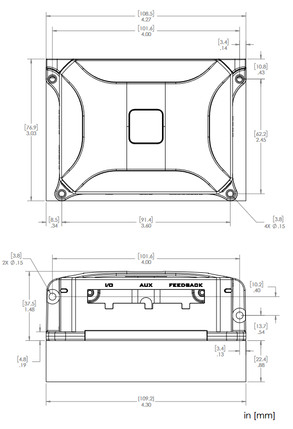
Figure 15: ION/CME 500 Dimensions
Additional Resources
- ION Digital Drives Datasheet
- ION/CME Digital Drive User Manual
- C-Motion Engine Development Tools Manual
- Servo Motor Tuning – Rocket Science or Walk In the Park?
- Step Motor Noise and How To Fix It
- Principles Of Motor Selection