We wrap up our deep dive series on how to diagnose common motion control problems and get your machine back on track!
In this deep dive we provide the third and final entry of a multi-part deep dive series on how to fix common motion control problems.
My Servo Axis Isn't Tracking As Well As I Want
Many applications only focus on final settling position. For those applications, the position tracking error (the difference between the commanded position and the actual position) only matters as the load comes to a stop.
For other applications, most notably machine tools but also including glue/sealant application, plotters, scanners, guidance, and more, the servo error matters during the move. If your dynamic tracking accuracy isn't as good as you need for your application, what can you do about it?
Use velocity and/or acceleration feedforward
The position compensation loop, which is often, but not always, a PID (Proportional, Integral, Derivative) loop, continuously tries to have the actual position equal the commanded position. Any external perturbation will make the job of the PID harder and thus increase the tracking error.
Forces that arise from the motion of the load itself, particularly acceleration and deceleration, are one such category of perturbation. Acceleration feedforward is a simple technique that attempts to pre-adjust the motor command output using the value of the motion controller's trajectory commanded acceleration.
Applying acceleration feedforward is done by adjusting a gain factor that tells the controller "when I accelerate at this rate, you can expect this motor output command to compensate for the resultant perturbation".
Knowing the load helps here because the reflected torque at the motor is proportional to the mass (the inertia) of the load. Conversely, if the load is unknown and varies substantially, this technique may not work very well.
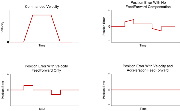
Figure 1: Feedforward Compensation
Velocity feedforward is similar, and is applied whenever a motor command correction that is proportional to the trajectory generator's velocity is needed. This occurs with some types of friction, and when the amplifier does not provide a current loop (voltage mode) due to back-EMF (electromotive force).
For a more detailed discussion of velocity and acceleration feedforward as well as other torque compensation techniques, see my previous Torque Feedforward deep dive.
You may also be interested in: Feedforward in Motion Control - Vital for Improving Positioning Accuracy
Fine tune your servo parameters
The higher you crank up your servo gains, the more rapidly the compensator can correct for external perturbations, and the less position error can build up. That’s the good news. The bad news is that as anyone who has tuned a system servo knows, you cannot simply crank the gains up forever. All too quickly the system will become unstable and you will have to back off.
So to minimize servo lag, you want servo gains that are aggressive but stable. To get started, take a look at a past Servo Tuning deep dive, that tells you how to tune your system.
To go further, you can use bode plots, or even attempt mathematical modeling of your motor and mechanics. Both of these techniques are beyond the scope of this deep dive, but may provide insights, if not actual improvements, to your system's performance!
Fancy filters
If you have pushed the limit on servo tuning optimization, there are a few additional filtering techniques that you may want to try to reduce servo errors further, although these tend to have their limitations.
The most common general approach is to apply some frequency-specific filtering, for example a low pass filter to your control system. This is usually done via a bi-quad filter. If your system supports these, you can try constructing a low pass or band pass filter to see if they can improve performance.
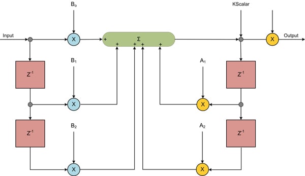
Figure 2: Bi-quad Filter
This motion control technique can work well if your mechanics have one, or perhaps two specific frequencies at which the load resonates. How do you find out where your system resonates? Do a frequency sweep of the mechanics by driving the motor with a sinusoidal waveform and measuring the servo error as the frequency increases. Bumps in the response curve indicate that the load is more resonate at those frequencies.
Another general technique you can try, although your controller may or may not support it, is to switch from a position-only loop such as a PID, to a filter that uses an inner velocity loop and an outer position loop. Called a cascaded position/velocity loop, this type of compensator may lower your servo lag.
We will discuss the challenge of velocity measurement further on, but one advantage of separating the position loop from the velocity loop is that special velocity estimation hardware, known as a 1/T circuit, can be used to estimate velocity. Another approach that can be used to build a velocity estimate from a fundamentally 'granular' digital input is a FIR (finite impulse response) filter.
Make sure the sampling time is adequate and optimal
In today's era of blazing fast digital motion controllers, a servo loop rate that is too slow is rare for all but the most exotic (read that tiny and fast) mechanical systems. Nevertheless, if you have concerns, you can check that the time constant of your system is much larger than the sample time.
This is not necessarily a trivial exercise, but one way to get an idea of the system's time constant is to measure the response to a step impulse. The time constant is roughly defined as the time it takes to reach 63% of the full impulse request.
Ironically, you may find that your performance improves if you decrease, rather than increase, the sampling speed. This is because in digital sampling servo systems, high frequency adjustments can inject noise in your axis. A lower sampling time may help lower some of this injected noise, reducing tracking error.
The kissing cousin of changing the overall servo loop rate is to change just the derivative (of the PID) sampling rate. If your controller allows this, you can try this as well.
Consider a dual position loop
A dual position loop, usually called a dual loop for short, measures the load position with one encoder, and the motor position with a second. For some types of mechanical setups, this loop can provide excellent results for the modest increase in cost of an additional encoder.
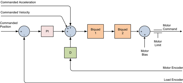
Figure 3: Dual Position Loop Flow
There are several ways that the second feedback can be wired into the loop compensator, but most use the motor encoder to stabilize the servo loop, and the load encoder to drive the actual position error to zero, or as close as possible. For the motion controller to support a dual loop it needs a second encoder input channel, a configuration that is also referred to as 1 1/2 axis of control.
Bear in mind that dual loops cannot work miracles. If the mechanical linkage between the motor and the load has a lot of compliance, the system response time will be slow and the resultant servo errors at the load will still be high.
Use sinusoidal commutation or FOC (Field Oriented Control)
Brushless DC motors that are commutated with a traditional "6-step" scheme are susceptible to discontinuities at the Hall sensor boundaries. Discontinuity here can be translated to 'perturbation' and thus increases the tracking error
A subtler effect related to the use of Halls is that the torque output of the motor is less linear. Although the magnitude of this effect depends a lot on how your motor is wound, actual torque output using Hall commutation, even if the motor given a constant torque command, can vary over the course of a single electrical cycle by 15% or more.
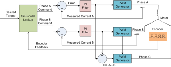
Figure 4a: Sinusoidal Commutation
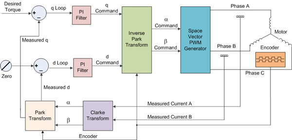
Figure 4b: Field Oriented Control (FOC)
Servo loops like to have nice, proportional response curves, so the more these variations in torque output at the motor can be eliminated, the better. See my Torque Control deep dive for more information on smoothing out torque bumps at the motor.
You may also be interested in: Field Oriented Control (FOC)
Take a close look at the mechanics
There are many aspects of a machine's mechanics that may increase its dynamic tracking error. Couplings, gears, bearings, slides, cables, and all manner of other mechanical components may be a source of torque perturbations.
Broadly speaking, the more 'direct' the mechanical connection between the motor and the load the better, with (you guessed it) a direct drive motor configuration being the gold standard for mechanical simplicity and stiffness.
Even here though, variations in friction along the track of motion due to ball bearing circulation, imperfect bearing slide tracks, variations in bearing tightness, and other factors may result in undesired servo errors.
Remember that the servo tracking performance is only as good as the mechanics it is being asked to control. Tighten and smooth out the mechanics, and tracking will improve.
I Need Better Motion At Low Velocity
There are a lot of servo motor applications that require smooth motion at low velocities. With the popularity of quadrature digital encoders this is big challenge because digital feedback is inherently granular, and the slower you go, the 'bumpier' things get.
So what's the best way to smooth things out?
Use a higher resolution encoder
The simplest solution by far is to reduce the granularity of the position feedback and go to a higher resolution encoder. This will give the PID filter more information to work with and should result in more accurate low speed tracking.
Slow down the sample rate
As was the case for the previous motion problem, slowing the sample time down may help motion smoothness because this averages position over a larger amount of time. Depending on the dynamics of your motor, you will only be able to slow the sample rate down so much, but this may still be a good approach to lower jitter.
Juno is designed to tackle of your velocity and torque requirements. Meet Juno!
Consider a 1/T velocity estimator
It makes intuitive sense that to control velocity, it is important to have an accurate measurement of the motor velocity. Interestingly, PID loops actually avoid this need because they work strictly by subtraction of successive captured positions. By the same token, a PID loop may not be the best compensation scheme for low speed servo motor control.
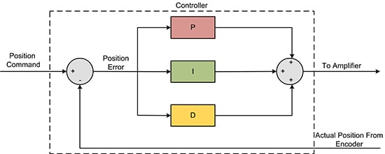
Figure 5a: PID (Proportional, Integral, Derivative) Loop
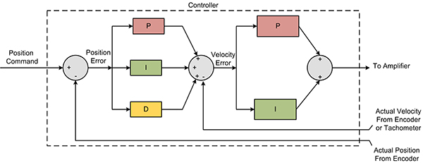
Figure 5b: Cascaded Position Velocity Loop
The cascaded position/velocity loop, mentioned above, may be a better approach. For this system, an accurate measure of velocity is key. Enter the 1/T estimator, which relies on the fact that the spacing between quadrature lines is usually very consistent.
Here's how it works: As the motor rotates, a measurement of the amount of time between successive same-phase quadrature transitions is used to give you an accurate estimate of velocity. A high speed digital counter is used, and a DSP or microprocessor takes the value of this "T" register, and calculates the actual velocity by calculating the quantity K/T, where K is a constant proportional to the time-base of the T measurement.
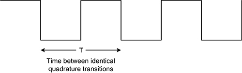
Figure 6: "T" Register
There are two main complications with a 1/T approach. The most important is that the velocity has to be high enough that a time capture occurs (allowing a velocity estimate to be calculated) at each servo sample time. As the velocity gets higher, the opposite problem occurs. At some point, estimating the velocity by successive subtraction of positions will give a more accurate measure than the 1/T technique.
So for serious general purpose compensation loops that utilize this approach, a hybrid velocity estimator algorithm must be constructed that provides a velocity value below, at, and above, the 'sweet spot' of hardware 1/T estimation.
All of these considerations together, the technique has merit but is not used that often. Also, it is not a feature offered by most off-the-shelf motion control vendors. So you may have to search a bit to find a vendor that offers it, or plan to construct it yourself.
Consider a tachometer
With the advent of digital controllers, analog tachometers are not used as often as they used to be. For low speed control however you may consider one to provide an explicit velocity-proportional signal that can be used with a cascaded position/velocity loop, described earlier.
If you use a tachometer with the right speed-to-voltage scaling, you can dramatically improve low velocity smoothness. Unfortunately, many off-the-shelf motion vendors don't support tachometer input, and the cost of a higher resolution digital encoder may be less than the cost of adding a tachometer into your digital control system.
Consider a phase locked loop controller
A phase locked loop is a special type of circuit that can determine the phase of an incoming signal such as a sin wave or a quadrature square wave. By arranging the output of a phase locked loop detection circuit to drive a motor, very accurate control of the motor's velocity can be achieved.
Negatives to this approach are that it only works for relatively constant speed movement. If your application requires a broad speed range, quick velocity changes, or reversals of direction, a phase locked loop will not work.
To bypass this problem, it is possible to construct a hybrid controller where a traditional PID loop or cascaded position/velocity loop is used to bring the axis to an approximate velocity, and a phase lock loop is used to then take over.
Unfortunately, most general purpose motion control systems do not offer phase locked loop control. On the plus side, they exist for special applications such as bar code scanners and other constant-speed motion applications.
Consider using a gear motor or other reducer
As old-school as it may sound, a reduction gear motor or pulley system of some kind may be the best approach toward achieving low speed motion in your application.
The main problem that can occur with reducers is the introduction of backlash and/or gear mate-up noise. The range of choices is broad, however, so you should also consider capstan/drum type reducers, cable-based reducers, and other reducers.
Here again, a dual loop architecture may be used to good effect. A position encoder is placed on the main slow-moving axis, ensuring accurate positioning, while a second stabilizing encoder is placed on the motor axis connected through a reducer ensuring smooth and accurate velocity control.
My Serial Network Is Too Slow
You may be surprised to learn that serial networks are still used in a very large number of applications to control and coordinate motion axes. This is true even for brand new machines where other network choices were available.
Why is serial still so popular? Cost is a big factor. So is ease of use. Engineers are familiar with serial (whether RS232 or RS485), making it easy to setup, and easy to use.
Here are a few suggestions for getting the most out of your serial network, and a few suggestions for higher speed networks if it comes to that.
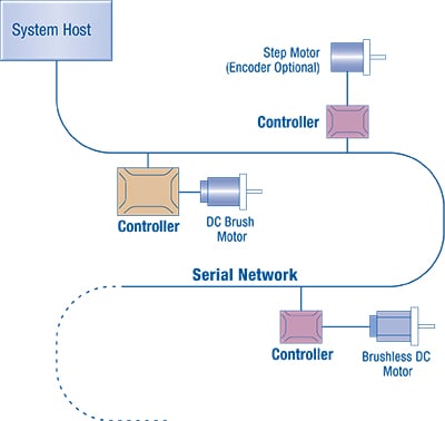
Figure 7: Application Network
Pre-load motion profiles
Most off-the-shelf motion controllers allow at least 'the next' move to be pre-loaded and executed upon some specific set of conditions.
Pre-loading means sending the next move, whether it is a velocity segment, a new point to point S-curve move, or a new electronic gear ratio, to a 'reserve' buffer. In addition, you specify what conditions will cause the reserve move to start automatically. When the condition becomes true, the pre-loaded move automatically becomes the active move and the axis takes off instantly.
By way of example, in the Performance Motion Devices system of control we call these conditions breakpoints, and include options such as 'start after a specific location has been reached', 'start at a specific time', 'start the instant the previous move has occurred', 'start when an external signal condition has occurred', etc.
Whichever machine controller you are using, the trick is to put the local motion engine in charge of starting the next move.
Up the baud rate
Using a higher baud rate is an obvious approach toward achieving better throughput, and most serial-based motion modules can process commands at 400Kbaud or higher.
There are a few things to watch out for though. If you are prototyping using a PC you are probably using the native baud rate of 56K. Purchase a serial card or USB to serial converter to achieve higher baud rates.
Beyond that, commanding motion networks from a PC can be tricky because PCs running most versions of the Windows operating system are not 'real-time'. PCs, even with their immense processor speeds, are notorious for spending precious milliseconds servicing a disk drive or other peripheral and in the meantime, suspending execution of your program.
Push some of the control functionality to the axis controller
If your current motion controller is designed to accept low level commands like 'move axis #1 to position X', 'move axis #2 to position Y", you may want to consider keeping the network, but upgrading the module/card so that you are now sending commands like 'extend arm', 'retract arm'.
In this approach, you will write software that resides in the module, knows what these higher level commands mean, and locally (read that at high speed with no network delays) processes them as complete sequences.
To make this practical, your motion software should be seamlessly relocatable in the PC or in the module.
Get a new network
Finally, you may want to use a faster, more flexible network. By way of general purpose highly flexible control networks, Ethernet is probably your best bet. The connectors and cables are cheap, and an increasing number of vendors offer Ethernet connectivity to their cards and modules.
At PMD Corp, we have had fun controlling our Ethernet-based motion controllers from a distance of thousands of miles over the Internet. This may or may not be useful to you (I suspect not!) but Ethernet does have the advantage that it can also be used for functions such as remote diagnostics.
Remember that Ethernet, while fast, is not deterministic, so depending on the nature of your control problem other networks such as CANbus, CANopen, EtherCAT, Ethernet Powerlink, or Profibus may be a better choice.
For more info on motion bus choices, see a deep dive on Motion Control Networks.
Did you miss Part 1 & II of the series? Here they are!
- Common Motion Problems and How to Fix Them - Part II
- Common Motion Problems and How to Fix Them - Part I
You may also be interested in:
- New Control Technique Combines Servo Performance With Step Motor Cost
- Improve Liquid Handling Robot Throughput with Direct Path Planning
- Feedforward in Motion Control
- Optimizing A Control Architecture for High Accuracy Syringe Dispensing
- Servo Tuning - A Deep Dive
- Field Oriented Control (FOC) - A Deep Dive
Design high-performance, reliable motion control applications. Get the latest articles, tips and news delivered right to your inbox. Subscribe to our quarterly newsletter.