With positioning motion control applications, one position feedback device has been the king of the hill for a long time - the incremental optical encoder with quadrature output. Having very low cost, good enough resolution, and good enough ruggedness, the incremental optical encoder dominates the market in many applications. However, as it often happens, what was once 'good enough' for some applications is - no longer. And, in some applications, the incremental optical encoder never was good enough for environmental or performance reasons. This deep dive will provide a survey of encoder types and the just-as-important subject of the data formats that are used to carry and encode position information.
What is an encoder?
Simply, an encoder is a device, circuit, software program, algorithm or person that converts information from one format or code to another. As it relates to motion control, encoders are used in machine designs that require motion feedback and motion control such as position (incremental or absolute), count, and direction.
The A, B, Indexes of Encoders
The basics of sensing position begin with the motor and mechanism that we will measure. Broadly speaking, encoders come in rotary or linear configurations, reflecting, not surprisingly, the two major types of motor actuators: rotary and linear.
Figure 1 shows a basic rotary optical encoder that outputs position information in quadrature format using two wires, 'A' and 'B'. The encoder also provides a once-per-rotation index pulse. The most common method used for constructing this encoder is using an array of opaque and transparent segments arranged so that when rotated, the A & B output signals are 90 degrees offset, as shown in the diagram below. The A, B and Index signals are created from LED (light emitting diode)/sensor pairs in the unit's electronics.
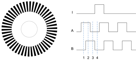
Figure 1: Incremental Rotary Optical Encoder
An index pulse provides a brief output signal once every rotation of the motor completes. This signal can be used during homing, or for automatic count loss correction.
Did You Get Lost?
In most quadrature encoders, the 'A', 'B' and 'I' signals are differentially driven to reduce the chance of losing counts through extraneous electrical noise. But this is far from foolproof, particularly in harsh environments.
Many motion controller products, including PMD Corp's Magellan® ICs, automatically correct for encoder count losses using the index. Since this pulse should always occur at exactly the same point of the motor's rotation, it is reasonable to assume that if it is received a bit 'early' or a bit 'late', incremental counts have been lost and to auto-correct for those losses.
In addition to count loss during movement, the other limitation of an incremental encoder is that the system does not know where the motor is upon wake-up. For many systems, this is easily corrected with a homing sequence, but for other applications, it is necessary to know where you are at all times.
Absolutely, I Use Optical Encoders

This brings us to the second major category of position encoder types - absolute position encoders - of which optical absolute position sensors are the most common. As the name implies, these encoders know where they are at all times. For rotary motors, they come in single-turn or multi-turn versions and output in binary word format, or an alternate format especially adapted for encoders called Gray Code.
Some absolute encoders with parallel-bit interfaces have thick wire bundles to carry 14, 16, 18 or more bits of position information. Increasingly though, absolute encoders use serial data formats such as SSI (Synchronous Serial Interface) to reduce the number of wires to communicate position to the motion controller. We will discuss various types of data formats for encoders a bit further in the paper.
Absolute encoders come in a wide range of resolutions. High-end units can provide a remarkable 25 bits of resolution, and even more. To ground that number in reality, 25 bits means 225 or 33,554,432 separate resolvable locations. In a single-turn rotary encoder, this means an angular resolution of 0.0386 arc seconds!
Extrapolate This
The sensing mechanism for high-resolution optical encoders tends to be more complicated than etched arrays of opaque/transparent LED/sensor pairs, such as those used in the standard quadrature optical encoder.
The subject of many recent patents is a seemingly ever-expanding galaxy of techniques that use phenomena such as interactions between multiple disks to create higher accuracy output signals. Most of these techniques, in one way or another, rely on the generation of nearly math-perfect multi-phase waveforms which are then electronically extrapolated to increase accuracy.
But There Is A Fog Bank In My Motor
Are there position encoders that can operate without optics? The answer is yes. There are several reasons why this might be advantageous. The most common is the ruggedness. In dirty, greasy, high shock environments optical encoders may be too delicate.
Historically, the most common non-optical position encoder is the: ResolverIt uses an arrangement of motor-winding-like coils that induct current to generate sinusoidal A and B output signals. Resolvers require no electronics in the sensor and can, therefore, operate at very high temperatures and in very harsh environments. Resolvers do need electronics to work with digital controllers, but these are located outside of the motor/sensor. Known as R/D (resolver to digital) circuitry converters, this circuitry converts the analog resolver signals into incremental or absolute digital position information.
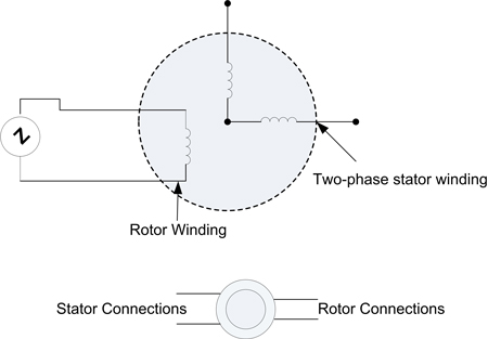
Figure 2: Resolver non-optical position encoder
Another position encoder type, one that is rapidly gaining in popularity, is the: Magnetic EncoderThis type of encoder uses a galvanomagnetic or magneto-resistor sensing element and typically outputs in quadrature format. Resolutions tend not to be that high, similar to low-end optical quadrature encoders (although increasing rapidly as the technology matures). The big advantage of magnetic encoders is that the sensor and the encoding disk/surface are contactless and can therefore be completely sealed, leading to excellent tolerance of physically dirty environments.
An encoder that has found a niche in some applications is the: Sin/Cos EncoderEssentially a variation on the standard A, B quadrature sensing scheme, Sin/Cos encoders output sinusoidally varying A and B signals rather than digital A and B outputs. These sinusoidal outputs, which are 90 deg out of phase with each other, can be used to electronically extrapolate position resolution, extending the encoder's performance.
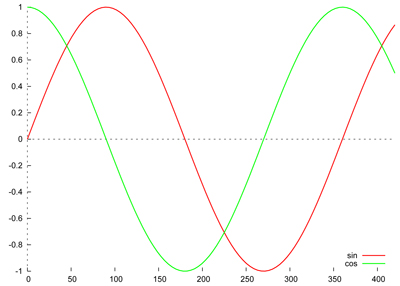
Figure 3: Sin/Cos Encoder Output Signals
One final sensing approach that has found wide adoption in positioning motion systems is the: LVDT (Linear Variable Differential Transformer)This device, as the name implies, is used to measure linear displacements. It accomplishes this by measuring the current induced by a primary coil in secondary coils, which changes based on the location of a ferromagnetic core tube attached to the moving axis. Like magnetic encoders, it is contactless and can therefore be completely sealed, which helps increase ruggedness. Unlike magnetic encoders, the output is an analog voltage and therefore needs to be converted by external electronics for use with a digital motion system.
You Encode Me
We began the discussion of encoders with the venerable optical incremental quadrature encoder. The quadrature encoding format still rules the roost for cost-sensitive systems. There are literally thousands of different encoder products that support it and virtually every motion controller accepts it.
In the next few paragraphs we will run through several other formats. Particularly as the machine control world becomes more network-centric, serial and network-based encoder data formats will gain popularity. And for high-end absolute encoders, which have evolved from providing 16 bits, to 20, to 24 bits and beyond, serial networks are rapidly becoming a defacto standard.
By far and away, the most common standard for dedicated serial encoder data networks is the: SSI (Synchronous Serial Interface)At the core, this interface uses a data signal and a clock signal to transmit position data from the encoder to the host controller. The clock signal can be arranged so that position updates are synchronized with the controller's servo sampling time. After adding support signals and differential encoding, SSI encoder cables can have anywhere from 6 to 10 wires.
A newer serial network, conceptually similar to SSI but adding some twists such as higher data rates and direct support for Sin/Cos encoders, is the: Endat serial interfaceAlthough gaining in popularity, one caveat is that it is still proprietary, having been developed by Heidenhain. Whether or not it will become an open standard remains to be seen.
We Will, We Will Assimilate You
The other major category of data formats by which encoder data can be transmitted is local machine control data networks. Unlike SSI or Endat, these networks are used for general machine control, but they also have support for the encoding of position information.
Ultimately, whether or not you should consider network-connected encoders hangs mainly on - surprise - whether your machine will be controlled by that network. If so, it may be convenient to build a backbone that also incorporates the encoders.
Having said that though, many design engineers will use an overall machine control network yet still connect to the encoder by a different scheme, such as quadrature. This is because very few networks close the motors' position loop at a central controller, instead of leaving that to network-connected intelligent amplifiers.
In any case, here is a partial list of networks that can directly support encoders in one way or another:
- CANbus
- Ethernet
- EtherCAT
- Ethernet Powerlink
- INTERBUS
- Profibus
- DeviceNet
- FOUNDATION Fieldbus
To The Laboratory!
To wrap up our discussion of encoders and encoder data format, we have set up a simple demonstration in the PMD lab utilizing a linear stage and high-accuracy encoder.
This particular setup uses a Performance Motion Devices' ION Digital Drive, a Thorlabs Brushless DC (BLDC) linear stage and a Renishaw encoder with 10-nanometer resolution. The ION provides all motion control profiling and servo positioning using high-performance digital position and current loops. The ION accepts DC power, inputs the encoder signals and drives the three BLDC motor signals.
Video: Linear Stage Traversing The Width Of A Human Hair
The video shows the stage traversing the width of a human hair. The encoder here is accurate enough that each move segment, traversing only about 1/5th the distance of a human hair (~20 microns), was commanded to move more than 200 encoder counts, or about 100 nanometers per count!
The amazing thing is that there are encoders on the market that have a position resolution of one nanometer. A nanometer is indeed very small, firmly entering the realm of the size of individual atoms. Moving up in scale, a typical germ is about 1,000 nanometers and a human hair is about 100,000 nanometers in size.
Got a question? Don't hesitate to contact us!
PMD Motion That Provides High-performance Encoder Support
PMD has been producing ICs that provide advanced motion control of servo and step motors for more than thirty years. Since that time, we have also embedded these ICs into plug-and-play modules and boards. While different in packaging, all PMD products are controlled by C-Motion, our easy-to-use motion control language and is ideal for use in medical, laboratory, semiconductor, robotic, and industrial motion control applications.
Magellan Motion Control ICs
Magellan single and multi-axis Motion Control ICs are perfect for building your own machine control board from the ground up. They feature the latest in profile generation, servo loop closure, current control, profile synchronization, event management, and PWM (Pulse Width Modulation) signal output generation. These low-cost and easy-to-use ICs also are available in versions that support camming and synchronized multi-axis contouring via User Defined Profile Mode option.
Learn more >>
ION Digital Drives
ION Digital Drives have a Magellan IC at their core and combine this with a high power digital amplifier to create a compact rugged cable-connected module. Whether used for S-curve point to point moves, high speed spindle control, or your latest robotic design challenge, IONs are cost effective plug and play devices that will get your application up and running in a snap.
Learn more >>
Atlas Digital Amplifiers
Atlas Digital Amplifiers are compact single-axis amplifiers that provide high-performance torque control for Brushless DC, DC Brush, and Step motors. Atlas amplifiers come in both a vertical and horizontal mounting configuration and are available in three power ranges; 75W, 250W, and 500W. They are used for direct control of motor torque or in conjunction with higher-level motion controllers providing position or velocity control functions.
Learn more >>
You may also be interested in:
- Closed Loop Steppers Drive New Motion Control Applications
- Force Control in Actuators and Robot End Effectors
- Digital Current Loop Significantly Quiets Step Motor Noise
- Improving Liquid Handling Robot Throughput using Direct Path Planning and Obstacle Avoidance Programming
- Common Motion Problems and How to Fix Them - Part I