Liquid handling systems often use peristaltic pumps to deliver reagents and other fluids to test sites. Although smaller volumes of liquid can be delivered by plunger-style syringe pumps, larger liquid volumes often use peristaltic pumps because the transported liquid is isolated from the pumping mechanism. Peristaltic pumps however exhibit a pulsating flow behavior due to how the roller-wheels engage with the liquid tubing. Fortunately, these fluctuations are predictable allowing adaptive techniques to be deployed. In this paper we will examine these phenomena in more detail and demonstrate how high pumping accuracies are achievable with the use of an adaptive control method.
Introduction
Peristaltic pumps are commonly used to deliver larger amounts of liquid to a site where the liquid is needed. A typical peristaltic pump (Figure 1) consists of a pump housing, a spinning rotor driven by a motor/encoder, typically 3 or 4 rollers, and a flexible section of tubing. The rollers compress the tubing while rotating thereby moving pockets of liquid from intake to outlet. The advantage of peristaltic pumps is that only the tubing is in contact with the liquid. The disadvantage is that the discrete pockets create an unsteady flow rate (Figures 6a and 6b), resulting in difficulty delivering small, precise volumes of liquid. In higher-end peristaltic pumps, a Brushless DC (BLDC) motor with a quadrature encoder and Hall sensors is typically used. A BLDC motor/encoder lends itself well for a more sophisticated controls approach as shall be discussed in this paper.
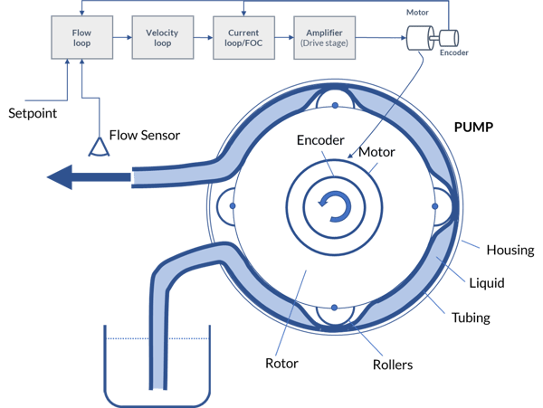
Figure 1: Peristaltic Pump Control Schematic
Figures 2 through 4 illustrate several methods of controlling the pump motor in a peristaltic pump. The simplest controller (Figure 2) applies a voltage to the motor without any form of feedback. The motor speed will depend on the applied voltage. Clearly this control gives no consideration the actual delivery velocity of liquid or the velocity of the motor as a result of the tubing compression and will thus result in the largest flow variations (Figures 6a and 6b). In addition, stopping the pump is imprecise, resulting in an unpredictable amount of liquid being delivered. For large volumes of liquid this may not matter since there are many pump rotations involved, but for smaller volumes this effect becomes important. Figure 3 demonstrates a control mode wherein encoder signals are fed back to a velocity control loop which is regulated by a velocity setpoint and Hall signals are fed back to a current control loop. The velocity loop outputs a torque command to a current loop (PI controller) and a Field Oriented Control (FOC) scheme which generates a PWM signal as an input to the amplifier. When one of the rollers starts compressing the tubing (or starts releasing it) the velocity changes and the torque delivered by the motor is changed as well, resulting in a more even rotor rotation. Depending on how “stiff” the controller is this will result in a fairly even velocity of the rotor and thus in even liquid delivery. Figure 4 is an enhanced version of the controller in Figure 3, wherein a flow compensation loop is added to the control scheme. This results in a system wherein the increases and decreases in flow from the rollers compressing the tubing is part of the feedback in the control system, thereby making the system stiffer than the controller in Figure 3 that is not aware of the actual flow rate changes.

Figure 2: Open Loop Voltage Mode

Figure 3: Velocity Loop Mode

Figure 4: Flow (and Velocity) Loop Mode
However, in such a system, the reaction speed of the flow sensor has to be faster than the actual changes in flow. This can be accomplished with turbine-based sensors as well as non-contact sensors such as ultrasonic sensors. This controller, by measuring the actual flow rate, gives a more robust compensation mechanism particularly at low velocities.
You may also be interested in: Precision Fluid Handling: It's All in the Pump
Selecting the Motor Type

Figure 5: Power to Weight and Torque Across Motor Types
Figure 5 shows some general performance characteristics for Brushless DC, DC Servo, and stepper motors. Brushless DC motors typically provide the highest figures of merit for power output to weight, which can be important for mobile pumping applications. DC Brush motors under servo control can also be used in the peristaltic pump application but have the big disadvantage that they use mechanical brushes for commutation. These brushes can wear or begin to deliver uneven torque as they age.
Stepper motors are also a candidate for this application especially if a control technique called closed loop stepper is used. This technique uses an encoder to operate the step motor as a two-phase Brushless DC motor. The result is significantly higher torque over the operating range of the motor because mid-range instability, a torque killer for open loop step motors, is eliminated.
You may also be interested in: Closed Loop Steppers Drive New Motion Control Applications
Despite these choices in motor type, the most popular choice for the peristaltic pump motor type is BLDC (Brushless DC) motors. Brushless motors with high resolution encoders driven by a position servo loop can achieve very high accuracy and can react extremely quickly to the changes in load that are inherent in peristaltic pump operation. Either geared or direct drive BLDC motors can be used, but increasingly direct drive is preferred because it avoids compliance and backlash which are inherent to use of a gearhead. Direct drive means the brushless motor will be able to follow the commanded position or velocity profile very accurately.
A key control technique for direct drive BLDC motors is sinusoidal (also known as encoder-based) commutation. The standard method of commutating brushless motors uses Hall sensors and defines six commutation states, one per 60 electrical degree interval. These square wave drive waveforms can result in torque output discontinuities. Encoder-based commutation can define many more than six states which allows sinusoidal waveforms to drive the BLDC motor phases. The result is more accurate torque output and improved rotational smoothness.
Method
In our experiments we used an FPU 500 pump from Omega coupled with a BLDC motor with Hall sensors and a 2,000 count (500 line) quadrature encoder. The controls were provided by a Performance Motion Devices Juno® MC78113 Developer Kit board with on board amplifier. The Juno IC was running a current loop (PI) at 20 kHz and a velocity loop at 200 Hz (when used). A McMillan model S-111 flow meter with a range from 13-100 mLpm and 1.0% accuracy and 0.2% repeatability and less than 1 second response time (full scale) was used for the controller in Figure 4. Operating the pump with 4mm tubing we were able to easily achieve a flow rate of 20 mLpm (20% of full scale) at a rotation speed of 0.5 rps or 30 rpm. Since the Omega pump employs 3 rollers spaced at 120 deg, we see that a roller transfers along the sidewall of the pump housing in approximately 1.5 seconds.

Figures 6a: Open Loop Voltage Mode

Figures 6b: Open Loop Voltage Mode - Frequency Analysis
For each of the 3 control schemes in Figures 2, 3 and 4, we measured actual flow as indicated by the S-111 sensor as well as the RMS and average motor torque and analyzed the dominant frequencies in the spectrum.
Figures 6a and 6b show the measured output of the open loop Voltage mode measurements. Figure 6a shows large variations in actual flow and Figure 6b shows that the dominant frequencies are around 0.5 and 2.1 Hz, corresponding to the motor rotation frequency and the roller rotation speed respectively.
Figure 7a and 7b show the same measurements for the Velocity Loop mode in Figure 3. As can be seen from the figures, the variations in actual flow rate are significantly reduced, and mainly the motor frequency (0.5 Hz) is no longer showing in the flow signal, although the variations caused by the rollers (2 Hz) are still clearly visible.

Figures 7a and 7b: Velocity Loop Mode
Figure 8a and 8b we show the results of the controller in Figure 4, which adds the outer control loop for flow to the velocity loop. As can be seen in the figures, the variations in flow are further reduced as are the peaks in the frequency spectrum.

Figures 8a and 8b: Velocity Loop Mode
You may also be interested in: Ventilator Control
Conclusion
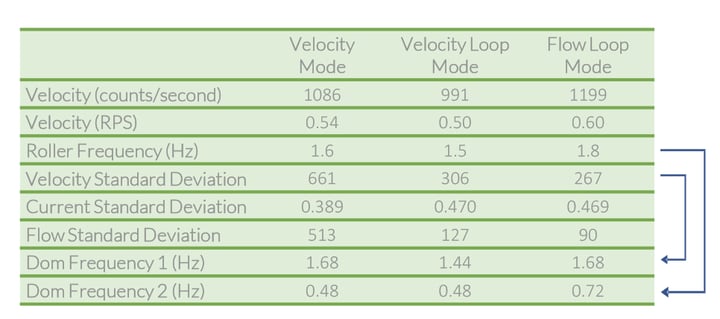
Figures 9: Results Summary
Figure 9 summarizes the above results and also looks at the standard deviations of the measurements. As can be seen in the figure, the standard deviation in the actual flow was reduced from 513 mL/min to 90 mL/min—an improvement of more than 5X. The control modes described in this poster lend themselves well for low flow operation of peristaltic pumps if the controller adds at least a velocity/FOC loop but can be improved even further with the addition of an outer control loop that integrates an actual flow sensor.
PMD Products That Control Pumps
Performance Motion Devices has been producing motion control ICs that provide advanced velocity, position, and torque control of DC Brush, and Brushless DC motors for more than twenty-five years. Since that time, we have also embedded these ICs into plug and play modules and boards. While different in packaging, all PMD products are controlled by C-Motion, our easy-to-use motion control language, and are ideal for use in medical, laboratory, semiconductor, robotic, and industrial motion control applications.
Juno Family of ICs
The Juno family of ICs are perfect for building your own low cost, high performance pump controller. Juno ICs excel at velocity and torque control, with features such as FOC (Field Oriented Control), profile generation, high/low switching amplifier control signal generation, leg current sensing, and more. Available in packages as small as 7mm x 7mm and costing $12 in quantity, these ICs are an ideal solution for your next pump controller design.
Learn more >>
Magellan MC58113
The MC58113 series of ICs are part of PMD’s popular Magellan Motion Control IC Family and provide advanced position control for step, BLDC, and DC Brush motors alike. Standard features include support for CAM profiles, trapezoidal & s-curve profiling, direct encoder and pulse & direction input, and much more. MC58113 ICs have an advanced trace capability that lets you collect critical pump performance data as fast as twenty times per mSec, or as slow once a day. Whether used for pump control, laboratory automation, microscope controllers, or general-purpose automation, the MC58113 family of ICs are the ideal solution for your next machine design project.
Learn more >>
ION/CME N-Series Digital Drives
N-Series ION Digital Drives combine a single axis Magellan IC and a high performance digital amplifier into an ultra-compact PCB-mountable package. In addition to advanced servo and stepper motor control, N-Series IONs provide S-curve point to point profiling, field oriented control, downloadable user code, general purpose digital and analog I/O, and much more. With these all-in-one devices building a custom controller board is a snap, requiring you to create just a simple 2 or 4-layer interconnect board.
Learn more >>
You may also be interested in:
- Digital Current Loop Significantly Quiets Step Motor Noise (Article)
- Peristaltic Pump Control (Motion Application)
- S-Curve Motion Profiles - Vital For Optimizing Machine Performance (Article)
- The Components Make Miniaturization Possible (Webinar)
- Field Oriented Control (FOC) - A Deep Dive (Article)