Step motors are a long-standing and popular solution for motion applications that benefit from low cost and brushless (externally phased) operation. Step motors traditionally use an open loop microstepping control scheme, but the more advanced control technique called closed loop stepper is increasingly being used in its place. Coupled with motors specifically designed for that control technique, closed loop steppers are now finding adoption in a range of cost sensitive industrial applications such as textile machinery, coil winding, circuit board production, and pick and place machines where high rates of acceleration are critical.
Introduction
When it comes to step motors, the drive technique called closed loop stepper is making everything old new again and driving a burst of interest in the use of two-phase step motors – winning back machine designers who may have relegated step motors to the category of low cost but low performance.
At the core, closed loop stepper is a control technique that adds an encoder to the motor so that it can be driven like a servo rather than via the traditional open-loop approach. The fact that an encoder is needed means that truly low cost applications will not be good candidates for closed loop stepper. But for applications that need high torque output and high acceleration along with improved accuracy, closed loop steppers are increasingly a go-to solution because they can match or even exceed the performance of more expensive Brushless DC motors.
Microstep me
Step motors are multi-phase devices, meaning multiple motor coils are electrically excited to generate the stator magnetic field. The vast majority of step motors have two phases, which are wired as two separate DC coils and driven with one coil 90 degrees ahead of the other.
Step motors are usually constructed with 1.8 mechanical degrees per full step (a full step is 90 electrical degrees). So this means a 1.8 degree stepper has 200 full steps per mechanical rotation. But significantly, for use in closed loop stepper applications a new breed of motor with 3.6 degrees per full step or even higher is becoming common.
To understand closed loop stepper control picture the force profile created by the combination of the rotor angle and the stator angle (technically the rotor magnetic flux angle and the stator magnetic flux angle) from 0 to 360 electrical degrees. The resultant force created by these two magnetic fields varies sinusoidally. In a microstepping control scheme, the rotor settles at the equilibrium position. The more current that is driven through the coils, the more flux generated by the stator, thereby creating a greater depth of the force valley.
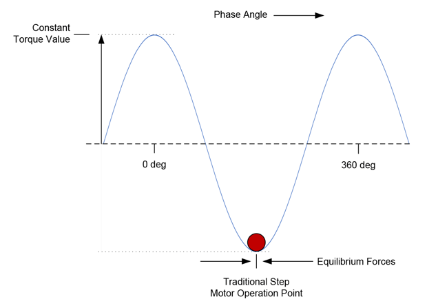
Figure 1: Traditional Step Motor Drive Scheme
To create motion the controller moves this valley forward or backward by changing the stator phase via the external coil connections. The motor rotor then ‘falls’ forward or backward, maintaining itself at the bottom of the force valley in response. Think of a ball settling to the bottom of a trough.
Closing the loop
As convenient and simple as this scheme is, it has a number of drawbacks including a tendency to oscillate around the settling point. This occurs due to the fact that nothing explicitly holds the rotor at the equilibrium position. Particularly when abruptly commanded to a new phase angle, the rotor will take time to settle to a new equilibrium position.
Another significant problem is heat generation. This occurs because the control is open loop with no way to adjust the commanded current according to the needs of the system and load mechanics. Therefore the motor, to avoid losing steps, must be driven at a high current level sufficient for all possible operating circumstances.
Now let’s look at the same diagram under closed loop stepper control. When the motor coils are excited they are not driven to a pre-determined phase angle. They are commutated, meaning the phase angle is driven to an angle according to the motor rotor location. In addition, the step motor is run like a servo motor with the coil current continuously varying according to a position PID loop. This means only the actual amount of current needed to generate a particular torque is used. So a big advantage of closed loop stepper is greater operating efficiency and less heat generation.
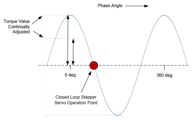
Figure 2: Closed Loop Stepper Servo Operation Point
Other advantages are that lost steps are eliminated because the encoder explicitly tracks the motor position. Even if the step motor falls behind the desired trajectory the PID loop will adjust the current so that the motor eventually catches up.
Another advantage is better control over positioning resolution & accuracy. Since the encoder explicitly measures the location of the motor the positioning accuracy becomes unlinked from the step motor's degrees per step characteristic (as mentioned commonly 1.8 or 3.6 degrees per step). With closed loop stepper the position resolution is determined solely by the resolution of the encoder, and therefore a step motor could achieve 2,000 resolvable locations per rotation or 1,000,000 resolvable locations depending on the encoder used.
Along these lines, an important factor in the increased adoption of closed loop stepper is the availability of high resolution encoders at affordable costs. When a 3.6 degree step motor is used a typical encoder resolution to support accurate closed loop stepper commutation is 4,000 counts per rotation. In a mass market encoder world that is a very high resolution, and up until a few years ago would be prohibitively expensive. But new encoder providers and new position measurement techniques have brought a generation of encoders that are smaller and cost dramatically less.
Beyond these important advantages however, the 'killer app' of closed loop stepper is in fact, acceleration. It is primarily this feature that is driving its increased adoption in the market. For a given step motor, the effective available acceleration rate will be 2 to 3 times higher using a closed loop stepper technique compared to an open loop microstepping technique.
Are we in ludicrous mode?
The scope trace below provides an example of this, showing a 3.6 degree step motor, one designed specifically for closed loop stepper operation, accelerating from a standstill to full speed back to a standstill in 4.25 mSec, all the while never having a position error (the difference between the commanded position and the actual motor position) of more than a few encoder counts.
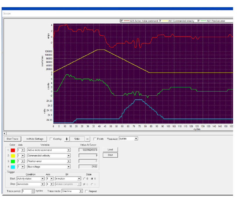
Figure 3: PMD’s Pro-Motion Screenshot
This screen capture is from PMD's Pro-Motion software package, which lets you trace four variables simultaneously at up to 20,000 samples per second. Most motion vendors provide a similar trace capability to help with application development and control parameter optimization.
In the above screen capture the commanded velocity is shown in yellow and the position error in green. The position PID motor output command is shown in red and the amplifier bus voltage is shown in blue. Note that the time units, which comprises the horizontal axis, are cycles (in this case the servo cycle of PMD's Magellan Motion Control IC), with one cycle having a duration of 51.2 uSec.
In this particular setup the motor accelerates from a velocity of 0 to 125,000 counts per second (30 revs/sec) in 37 cycles or 1.89 mSec for an effective acceleration rate of 15,850 rev/sec2.
What makes such high acceleration rates possible? In addition to the use of the closed loop stepper drive technique, a key factor is the step motor's ability to be constructed with a low inertia. Compared to Brushless DC motors which must have magnets in the rotor, step motors can use special thin disk designs without magnets to minimize rotor weight. Also, it is possible to design step motors with a higher pole count. More poles mean more torque which means more acceleration.
The other piece of the acceleration equation is the controller, which needs to run at a high speed to simultaneously keep the commutation angle correct, update the PID loop, and run an advanced control technique to maximize speed and drive. That control technique is typically FOC, which stands for Field Oriented Control.
The overall practical minimum update speed for a closed loop stepper controller is probably 5,000 cycles per second. The above system was driven by PMD's ION/CME N-Series Digital Drive which has a cycle rate of 20,000 cycles per second. It’s worth noting that low cost motion control ICs can also support closed loop stepper, and are now available at update rates of 10,000 cycles per second and above.
Summary
The decision to use a closed loop stepper is application dependent and based on the need for improved reliability, lower heat generation, and higher acceleration. This means medical devices and heat-sensitive scientific and laboratory equipment will consider closed loop steppers.
But due to new motor designs, lower cost encoders, and faster controllers, closed loop stepper is also becoming a go-to solution in a wide range of cost sensitive industrial applications such as coil winders, textile machinery, high speed pick and place actuators, and electronics and semiconductor equipment.
You may also be interested in: New Control Technique Combines Servo Performance With Step Motor Cost
PMD Products That Support Closed Loop Stepper
Performance Motion Devices has been producing motion control ICs that provide advanced precision and position control of step motor, DC Brush, and Brushless DC motors for more than twenty-five years. Since that time, we have also embedded these ICs into plug and play modules and boards. While different in packaging, all of these products are controlled by C-Motion, PMD's easy to use motion control language and are ideal for use in laboratory equipment, pick and place machines, and a wide variety of other high performance motion control applications.
ION/CME N-Series Digital Drives
N-Series ION Digital Drives combine a single axis Magellan IC and a high performance digital amplifier into an ultra-compact PCB-mountable package. In addition to advanced servo and step motor control, N-Series IONs provide S-curve point to point profiling, field oriented control, downloadable user code, general purpose digital and analog I/O, and much more. With these all-in-one devices building a custom controller board is a snap, requiring you to create just a simple 2 or 4-layer interconnect board.
Learn more >>
MC58113 Series ICs
The MC58113 series of ICs are part of PMD's popular Magellan Motion Control IC Family and provide advanced position control for step motors, BLDC, and DC Brush alike. Standard features include s-curve profiling, FOC (Field Oriented Control), high/low switch signal control, direct encoder & pulse & direction input, and much more. MC58113 ICs can control step motors in a closed loop stepper mode or via a microstepping mode. Whether used for laboratory automation, pump control, pointing systems, or general-purpose automation, the MC58113 family of ICs are the ideal solution for your next machine design.
Learn more >>
Juno Family of ICs
The MC74113 and MC74113N are members of the Juno family of ICs and are perfect for building your own low cost, high performance microstepping or closed loop stepper motor controller. Juno ICs feature FOC (Field Oriented Control), two-phase waveform generation, high/low switching amplifier control signals, leg current sensing, and more. Available in packages as small as 7mm x 7mm and costing $12 in quantity, these ICs are an ideal solution to upgrade your existing pulse & direction controller for closed loop stepper operation.
Learn more >>
More Motion Control Resources:
- Step Motor Noise - Common Motion Control Problems and How to Solve Them
- Feedforward in Motion Control - Vital for Improving Positioning Accuracy
- Build vs Buy Of A Three Axis Motion Controller
- Force Control in Actuators and Robot End Grippers On-demand
- Mathematics of Motion Control Profiles
- Multi-Axis Motion Control Chipset Provides Profile Generation, Servo Control, and Pulse & Direction Generation