This guide compiles ION/CME N-Series Drive application examples for Brushless DC, DC Brush, and step motors. High level control flow diagrams allow users to quickly choose and adapt an approach. Each description provides control modes, feedback and communication options, along with other useful system-level application information.
ION/CME N-Series Drive Summary
The ION/CME N-Series Drive is a compact, single-axis motion controller with integrated power electronics and network communications. Models are available to drive DC Brush, Brushless DC, and step motors, with multiple host interface options and power levels for embedded or distributed motion control applications.
The N-Series ION provides onboard profile generation and position, velocity, and torque control, along with functions such as encoder position feedback, servo compensation, brushless commutation, microstep generation, and digital current control. It includes integrated protection against overcurrent, undervoltage, overvoltage, overtemperature, and short-circuit faults, and supports host communications over Ethernet, CAN, RS232/RS485, and SPI, with additional CAN and SPI connectivity for multi-axis and peripheral connections.
Feature List
- DC Brush, Brushless DC and step motor control versions
- Ethernet, CAN FD, RS232/485, or SPI host communications
- 75 W, 350 W, or 1000 W power rating
- Ultra-small package (37.6mm x 37.6mm x 16.8mm)
- User programmability provides standalone operation
- S-curve, trapezoidal, velocity contouring, electronic gearing profiles
- 12-56 V single power source
- 20, 40, 80 and 120 kHz PWM frequency
- Supports quadrature, sin/cos, BiSS-C encoders
- FOC (Field Oriented Control)
- Programmable dual biquad filters
ION/CME N-Series Drive Typical Applications
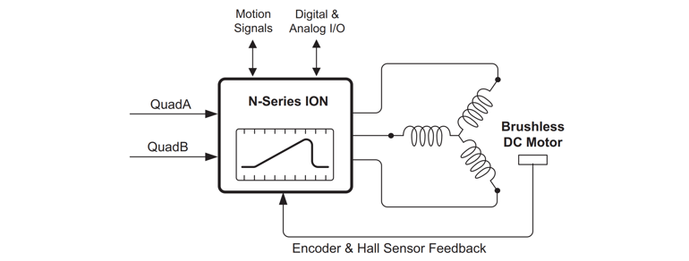
Position, Velocity, and Torque Control of Brushless DC and DC Brush Motors
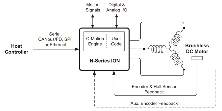
In this application the ION/CME N-Series Drive receives high-level motion commands from a host via an RS232, RS485, CAN, SPI (Serial Peripheral Interface), or Ethernet network and provides profile generation and position, velocity, and torque control of DC Brush or Brushless DC motors via a PID (Proportional, Integral, Derivative) servo control loop. Alternatively, command sequences can originate from user code downloaded into the ION unit’s C-Motion Engine.
Quadrature encoder, sin/cos, or BiSS-C format encoders or Hall signals are used for position feedback. For Brushless DC motors Hall sensors normally provide commutation feedback. If encoder signals are available however Halls are not required as long as the motor can move freely during startup. Additional signals include home & index inputs, directional limit switches, general purpose digital and analog I/O, SynchIn & SynchOut, Enable, Brake, FaultOut signals and an auxiliary encoder input channel.
Note that in the diagram above a Brushless DC motor is shown but similar control can be provided for DC Brush motors.
Additional Hardware Needed: The N-Series ION is powered directly via a single +HV voltage and provides all electrical functionality for this application. The only additional hardware needed is an interconnect board to connect the N-Series ION’s power, motor, and signal connections to external connectors. This functionality is typically provided via a user-designed interconnect board or the N-Series ION Developer Kit board.
Position & Velocity Control of Step Motors
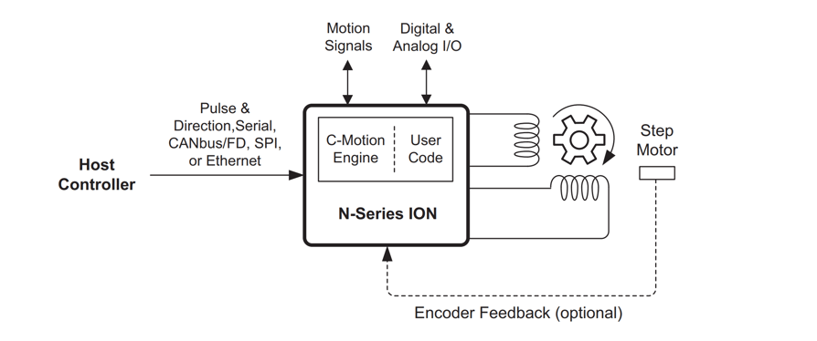
In this application the ION/CME N-Series Drive receives high-level motion commands from a host via pulse & direction signals, RS232, RS485, CAN, SPI (Serial Peripheral Interface), or Ethernet network and provides profile generation and position, velocity, and torque control of step motors using a microstepping drive scheme. Alternatively command sequences can originate from user code downloaded into the ION unit’s C-Motion Engine. Encoder feedback for stall detection is supported but optional.
Additional signals include home & index inputs, directional limit switches, general purpose digital and analog I/O, SynchIn & SynchOut, Enable, Brake, FaultOut signals and an auxiliary encoder input channel.
Additional Hardware Needed: The N-Series ION is powered directly via a single +HV voltage and provides all electrical functionality for this application. The only additional hardware needed is an interconnect board to connect the N-Series ION’s power, motor, and signal connections to external connectors. This functionality is typically provided via a user-designed interconnect board or the N-Series ION Developer Kit board.
Pulse & Direction Control of Brushless DC and DC Brush Motors

In this application a PLC (programmable logic controller), motion control board or other external controller provides pulse and direction commands to the ION/CME N-Series Drive which controls a servo motor such as a DC Brush or Brushless DC motor. The incoming pulse & direction signals provide the position command which is used together with a PID (Proportional, Integral, Derivative) loop to provide position control. Quadrature, sin/cos, or BiSS-C format encoders or Hall sensor feedback is used for servo motor position feedback. For Brushless DC motors Hall sensors normally provide commutation feedback. If encoder signals are available however Halls are not required as long as the motor can move freely during startup.
Additional Hardware Needed: The N-Series ION is powered directly via a single +HV voltage and provides all electrical functionality for this application. The only additional hardware needed is an interconnect board to connect the N-Series ION’s power, motor, and signal connections to external connectors. This functionality is typically provided via a user-designed interconnect board or the N-Series ION Developer Kit board.
Closed Loop Operation of Step Motors
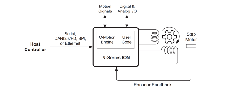
In this application the ION/CME N-Series Drive executes closed loop control (also called servo stepper operation) of a step motor. In this control mode the step motor is operated as a commutated two-phase servo motor. Relative to traditional microstepping step motor operation closed loop control provides smoother motion, less noise, higher acceleration, and eliminates the problem of lost steps.
Encoder input is required for closed loop step motor operation. Other than the approach toward step motor control, the features provided with this configuration are the same as for the previously shown step motor control typical applications.
Additional Hardware Needed: The N-Series ION is powered directly via a single +HV voltage and provides all electrical functionality for this application. The only additional hardware needed is an interconnect board to connect the N-Series ION’s power, motor, and signal connections to external connectors. This functionality is typically provided via a user-designed interconnect board or the N-Series ION Developer Kit board.
Force Control with Brushless DC or DC Brush Motors
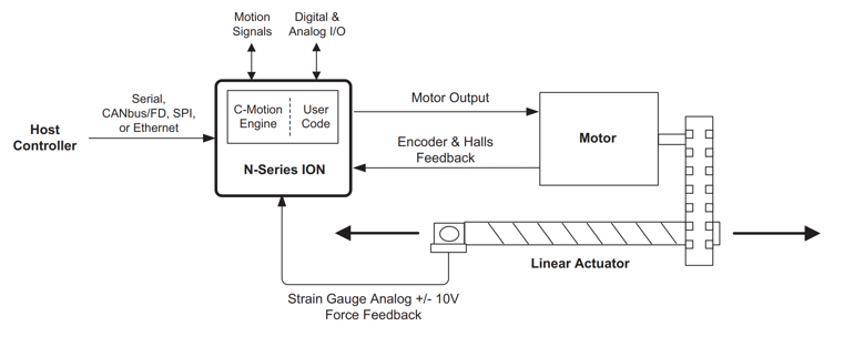
In this application the ION/CME N-Series Drive inputs a quadrature position data stream from an external encoder via its Auxiliary encoder input and uses it as the master rate command for execution of an internally stored cam or electronic gear profile. Prior to profile operation the cam shape is stored by the user in the ION unit. Execution of camming functions and of other complex shapes is enabled via PMD’s User Defined Profile Mode.
The above diagram shows a Brushless DC motor but similar control can be provided for DC Brush and step motors.
Additional Hardware Needed: The N-Series ION is powered directly via a single +HV voltage and provides all electrical functionality for this application. The only additional hardware needed is an interconnect board to connect the N-Series ION’s power, motor, and signal connections to external connectors. This functionality is typically provided via a user-designed interconnect board or the N-Series ION Developer Kit board.
CAM Profile Control of Brushless DC, DC Brush, or Step Motors
In this application the ION/CME N-Series Drive inputs a quadrature position data stream from an external encoder via its Auxiliary encoder input and uses it as the master rate command for execution of an internally stored cam or electronic gear profile. Prior to profile operation the cam shape is stored by the user in the ION unit. Execution of camming functions and of other complex shapes is enabled via PMD’s User Defined Profile Mode.
The above diagram shows a Brushless DC motor but similar control can be provided for DC Brush and step motors.
Additional Hardware Needed: The N-Series ION is powered directly via a single +HV voltage and provides all electrical functionality for this application. The only additional hardware needed is an interconnect board to connect the N-Series ION’s power, motor, and signal connections to external connectors. This functionality is typically provided via a user-designed interconnect board or the N-Series ION Developer Kit board.
Host-Connected Motion Drive Network
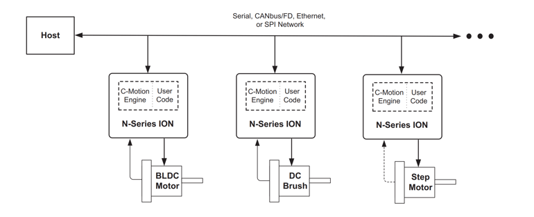
In this application one or more ION/CME N-Series Drives connect directly to an RS422, RS485, CAN, Ethernet or SPI (Serial Peripheral Interface) network and provide control of Brushless DC, DC Brush, or step motors. Commands are sent by the host to each N-Series ION to accomplish the overall machine function. In addition to N-Series IONs other PMD network-attached devices may be added to the network or non-PMD devices as well.
In some such distributed applications, the user application software is executed only in the host. In other applications, one or more N-Series IONs may also execute user-written code. Typically this would be done to distribute the machine’s overall computation load, to improve performance by locating the code in the drive itself, or to implement protocol translation if the host network must speak a particular protocol. Whatever the function of the code running in the N-Series ION, it is created by the user using PMD’s C-Motion libraries and downloaded to the N-Series ION, where it is kept in NVRAM.
Centrally Controlled Multi-Axis Motion Drive Network
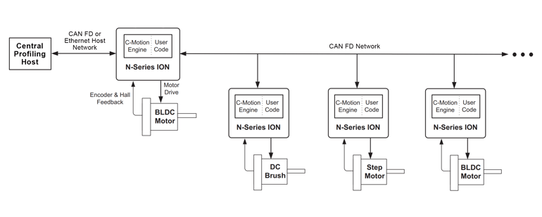
In this application a central profiling engine sends cyclic (rapid, repeating) position, velocity, or torque commands to a network of drives via an Ethernet or CAN FD network to an N-Series ION. This N-Series ION drives an axis and also parcels out the transmitted profile information to the CAN FD-connected N-Series IONs. Up to 16 or more axes may be controlled in this way from a single central profile generator.
The host-connected N-Series ION executes downloaded user code which processes the multi-axis profile data stream and sends it on to the CAN FD-connected N-Series IONs. Those N-Series IONs may utilize one of the standard provided profiling modes offered by the N-Series ION, or may contain user code which expands or optimizes the centrally controlled profiling scheme. In addition to profiling, data reporting may be implemented by each CAN FD-connected ION drive providing synchronized updates of encoder position, signal input states, or other status information.
Centrally controlled profiling applications are ideal for a range of applications including robot arm control, bipedal robot control, end effector control, CNC equipment, and other centrally controlled applications with high axes counts.
Locally Controlled Multi-Axis Motion Drive Network
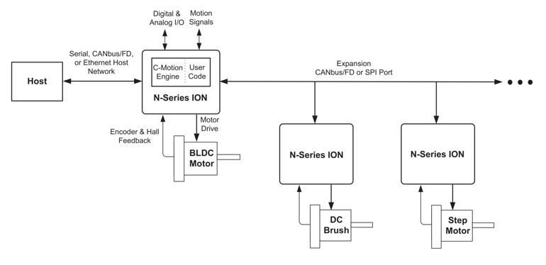
In this application an ION/CME N-Series Drive interfaces directly to an RS422, RS485, CAN, or Ethernet host network and acts as a multi-axis machine controller connected to the host network which sends high level commands associated with the function of the machine being controlled. The host-connected N-Series ION, which directly controls one motor axis, connects to additional N-Series IONs via its expansion CAN or SPI network
This is a similar application to the previously shown central control network configuration with the main difference being that the host-connected N-Series ION provides the high level machine control function using downloaded user code. The host controller does not provide a high speed cyclic profiling datastreams but rather sends high level commands which are interpreted by the host-connected N-Series ION. The code to accomplish this is created by the user using PMD’s C-Motion libraries provided as source code, compiled, and downloaded to the master N-Series ION’s code execution unit (C-Motion Engine).
Locally controlled applications such as this are ideal for a range of applications including gantry controllers, semiconductor equipment, indexers, SCARA arm controllers, XYZ tables, and much more.
Machine-Controller, PCB-Based
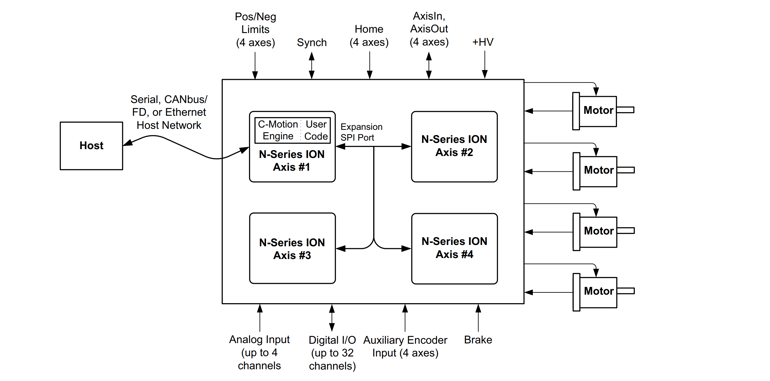
In this application an ION/CME N-Series Drive interfaces directly to a RS422, RS485, CAN, or Ethernet network and acts as the host network command processor and master machine behavior coordinator. This N-Series ION, which directly controls one motor axis, connects to three additional N-Series IONs via its expansion SPI or CAN port. This application is similar to “Machine Controller, Network Based,” except that rather than being cable-connected the IONs are all mounted on the same PCB (Printed Circuit Board).
This application is similar to the previous except use of the SPI expansion port is emphasized, which means all N-Series IONs are located on a single PCB. As for the previous described application commands to this multi-axis machine are processed by the host-connected N-Series ION, and motion sequences are partitioned as needed to the additional N-Series IONs via the SPI expansion bus connection. The code to accomplish this is created by the user using PMD’s C-Motion libraries provided as source code, compiled, and downloaded to the master N-Series ION’s code execution unit (C-Motion Engine).
Microprocessor Based Motion Controller, PCB-Based
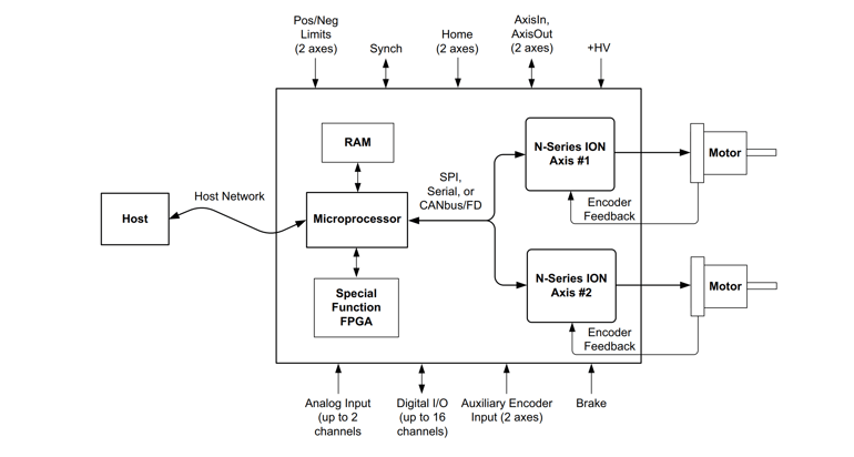
In this application a microprocessor connects to one or more ION/CME N-Series Drives via an SPI, serial, or CAN connection on a single PCB. In this application the user code resides in the microprocessor which commands the overall motion sequences. This application is similar to “Machine Controller, PCB-Based,” except that a microprocessor connects to the host network rather than an N-Series ION.
Use of a separate microprocessor for motion command sequencing may be useful especially where special computational requirements for the application exist or where special peripherals on the card need to be interfaced to that cannot be accommodated by an N-Series ION.
Standalone Controller with User Interface
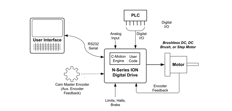
In this application an ION/CME N-Series Drive functions as a complete standalone controller. The Serial N-Series ION connects via its RS232 port to a user interface module which allows an operator to configure and control a cam profile function. The cam master encoder data stream is input via the N-Series ION’s auxiliary encoder input. Finally, digital I/Os from a PLC select various cam functions to execute.
PMD Products Featured in this Guide
The ION/CME N-Series Drive supports a wide range of motors and system architectures, as illustrated in the application examples provided. By integrating motion control, amplifiers, and network communications into a single module, the N-Series handles high-level motion tasks such as trajectory generation, profile control, feedback processing, and motor drive output within the drive itself. This integrated approach enables scalable, high-performance control of DC Brush, Brushless DC, and step motors.
ION/CME N-Series Drive
ION®/CME N-Series Drives are high performance intelligent drives in an ultra-compact PCB-mountable package. In addition to advanced servo and stepper motor control, N-Series IONs provide s-curve point to point profiling, field oriented control, downloadable user code, general purpose digital and analog I/O, and much more. These all-in-one devices make building your next machine controller a snap.
Learn more >>
You may also be interested in:
- PMD Positioning Motion Control ICs Applications Summary (Article)
- Dusty Robotics N-Series Case Study (Case Study)
- Mathematics of Motion Control Profiles (Article)
- Build vs. Buy of a Three Axis Motion Controller (Article)
- Feedforward in Motion Control - Vital for Improving Positioning Accuracy (Article)