
Machine designers are increasingly asked to build systems that take up less space, operate on less power, and run with higher performance. Thankfully motion controls are answering the call with new motors, new sensors, and new architectures. Read on to learn about the latest developments as motion control goes small.
Introduction
It seems that every day there are announcements of smaller and smaller motors, controls, and sensors used in precision motion control. What is driving these applications is the growing demand for motion control components used in surgical, patient treatment, mobile robotics, drones, and battery-powered applications. In this article we will introduce you to recent developments in motion control technology that are letting engineers build systems that use less power, make less noise, and take up less space.
We will look first at the motors themselves to understand how they are evolving and assimilating new sensor and control techniques to boost their performance. Then we will focus on controls to show not just how and why motion control components are physically shrinking, but how new control techniques are being used to maximize motor and system performance.
Finally we will look at how the evolution of motors and controls are impacting architecture. Because it turns out that smaller and more efficient controls allow entirely new approaches to where the controls are located, how they are wired, and how these changes are having a major impact on performance, reliability, and cost.
Mini motors 101
Figure 1 shows two graphs comparing various motor types in two key performance metrics: power output to weight, and torque output to weight. For a given application usually one of these two factors are more important than the other, and in fact, they are related because power is defined as torque times spin rate.
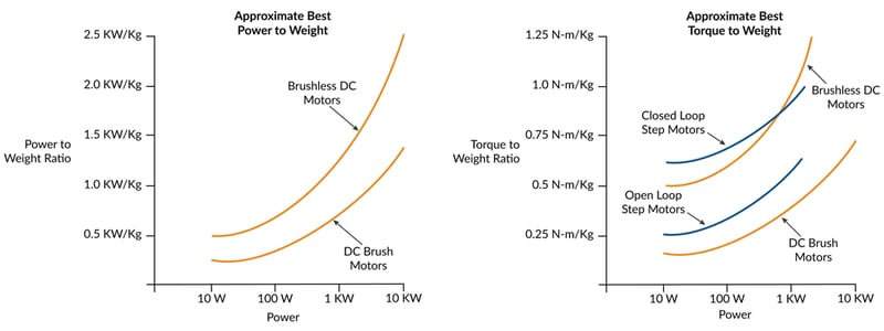
Figure 1: Comparison of Motor Types in Two Key Performance Metrics
As the graph shows, Brushless DC motors, with their ability to generate a constant torque up to a high spin rate, typically provide the highest figures of merit for power output to weight. Typical values are double the ratio of DC Brush motors. Step motors, although frequently used in portable applications, are not usually part of the power to weight conversation because their torque drops off rapidly as rotation speed increases.
If we instead want to optimize torque to weight, step motors are back on the table. Traditionally open-loop operated step motors have high holding torques, but their ability to deliver that torque over a working speed range is affected by their tendency to oscillate. Practically speaking, this means the effective torque delivered by the step motor is between 50% and 70% of the motor's rated holding torque.
There is an alternate way of operating a step motor however which largely solves this issue. A technique called closed loop servo, also called stepper servo, uses an encoder to operate the step motor as if it were a two-phase Brushless DC motor. The result is significantly higher torque over the operating range of the motor because mid-range instability, a torque killer for open loop step motors, is eliminated. More on this up and coming technique a bit later in the article.
I sense a change
An interesting aspect of the evolution of motor/actuators is how they utilize (or not utilize) sensors. As motors get smaller and smaller, and as they are implanted or strapped on to patients or used in mobile robots, it becomes harder and harder to add sensors without impacting the motor package size or the robustness of the motor/sensor combination.
So one trend affecting motors is sensorless operation - eliminating sensors and operating the motor using control techniques such as back-EMF (for Brushless DC motors) or electronic stall detection (for step motors).
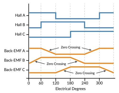
Figure 2: Back-EMF for Brushless DC Motors
There are simple and fancy ways to utilize the back-EMF of each winding of a Brushless DC motor. Figure 2 represents the most straightforward, measuring the back-EMF of a floating leg while the other two legs are being driven. The floating leg, no longer influenced by the drive output of the amplifier, contains the back-EMF voltage which can be used to determine the zero-crossing point, allowing a specific location of the commutation cycle to be determined.
Back-EMF works very well under the right circumstances but has so far not been adopted in general purpose motion applications. The first challenge is that back-EMF signals disappear as the velocity of the motor decreases. So, for all practical purposes sensorless Brushless DC applications cannot be used in positioning applications where the motor needs to be controlled around a stationary location.
In a velocity control application however sensorless drive has seen significant adoption. Although we still have the problem of not being able to sense back-EMF signals at low velocity, the controller can overcome this limitation by using a microstepping drive technique (operating the Brushless DC motor as a step motor) to bring it up to speed and then switching to back-EMF commutation once the measured back-EMF signal provides sufficient signal to noise.
When it comes to step motors, sensorless operation means more or less the opposite. Step motors can position all the way down to zero velocity but need help as the velocity increases, where they are prone to losing steps or having the motion collapse altogether. Sensorless electronic techniques can help by reducing the tendency to oscillate at certain speeds and by detecting that the rotor has stalled.
However the same "it works till it doesn't" limitation that applied for sensorless Brushless DC motors operation applies here as well. It is difficult to guarantee that electronic stall detection will work 100% reliably, so step motor applications that are really mission critical tend to use an encoder to confirm the motion.
When the going gets tough the tough get sensing
Strangely, motors of all types including very small motors are also trending in the opposite direction, upgrading their sensors to overcome the robustness limitations mentioned earlier, or adding sensors to motor types that previously did not use them.
Upgrading the sensor for robustness often means moving away from optical sensors, which are otherwise the workhorse of motor position sensing in the form of the quadrature incremental encoders. So to address the needs of harsh environment and medical applications there has been an uptick in the use of non-optical sensing solutions such as magnetic and capacitive encoders.
Shown in Figure 3, magnetic encoders can be hermetically isolated from the motor, measuring the position through a small air gap. The motor's rotor carries a magnetic encoding disk typically mounted at the very end of the motor shaft, while the electronic portion of the encoder uses either Hall sensors or magneto resistive sensing techniques to determine the rotor position. Magnetic encoders have leapt forward in resolution since their inception, and now can provide quadrature resolutions of 1,024 counts per rotation or more.
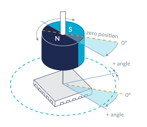
Figure 3: Magnetic Encoder Hermetically Isolated from the Motor
Capacitive encoders can also be hermetically sealed from the motor, and therefore have seen growing interest for use in harsh environment and medical applications.
Aiding the adoption of these new encoder types are improvements in the controls which use high precision A/Ds (Analog to Digital converters) and algorithmic techniques to compensate for small irregularities in the encoder's analog output signals along with fast arc-tan calculations to generate resolution-enhanced position values.
Funny, you don't act like a step motor
Step motors aren't normally operated with an encoder, but are now going through an evolution which relies on an encoder to operate the motor as a servo motor- essentially spawning the birth of a fourth motor type for positioning motion applications; after Brushless DC , DC Brush, and traditionally controlled step motors.
We will look at this technique in a bit more depth below, but the characteristics of this "new" motor type are very high acceleration rate, high torque to weight, and a reduction or elimination of the vibration issues found with normal step motors.
This new approach is driving the evolution of the step motor itself. For example, step motors used with the closed loop stepper control mode often utilize a 3.6 deg per step design rather than the traditional 1.8 deg per step configuration, and the rotors are becoming lighter to allow higher acceleration. Typical applications for the closed loop stepper include coil winding machines, textile equipment, high speed pick and place, die bonding, and others.
When the dust settles it seems that we will have two groupings of step motor designs, those designed to be traditionally controlled using full, half, or microstepping techniques without an encoder, and those designed to be controlled as a servo.
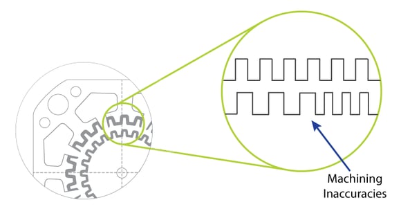
Figure 4: Step Motor Machining Inaccuracies
There is an interesting footnote to this that makes closed loop stepper particularly impactful for very small step motors.With traditionally-sized step motors such as NEMA 23 or NEMA 17 it is not all that difficult to machine the rotors and 'matching' stators consistently enough to maintain a consistent step size during motion.
As shown in the Figure 4 above, step motors have a large number of 'teeth' in the rotor, each of which should align precisely with corresponding teeth in the stator for optimum equal-step motion. As the rotor gets smaller and smaller though, the relative impact of small machining inaccuracies has a larger and larger impact on the performance of the motor.
Closed loop step motor operation, because of its ability to smooth over these underlying variations, is becoming an important technique allowing step motors to keep getting smaller and smaller without need for exotic and expensive machining techniques.
You may also be interested in: Advanced Motion Control of Servo and Step Motors
Honorable mention for the piezo motor
Before finishing our discussion of motors and motor sensors, another motor type, the piezo motor, deserves an honorable mention because 'very small' has always been its bread and butter operating domain.
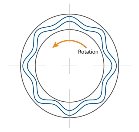
Figure 5: Schematic of the Piezo Motor
Figure 5 diagrams a rotary piezo motor. Notably, it does not use magnetics to generate torque. Instead it takes advantage of the tiny dimensional change of piezoelectric materials when subjected to an electric field. Utilizing this principle rotary piezo actuator controllers carefully excite the rotor disk to set up a standing wave whose phase can be changed electronically. The stator is effectively a very low-height gearhead that 'grabs' the rotor once the standing wave has been created. When the phase of this standing wave is altered, rotation occurs.
Functionally, piezo motors most resemble step motors. They excel at holding position or moving at relatively low speeds. Like a step motor they do not require an encoder to accomplish this. And despite the special drive electronics inside the motor, these actuators increasingly present a standard interface to the external world and are therefore compatible with off-the-shelf motion controllers.
So far Piezo motors have seen high volume adoption in specific consumer applications such as camera auto-focus and f-stop control, and have also seen adoption in applications such as ultra-high precision XYZ tables and pointing.
Given their ability to be produced in very small form factors (2 mm x 2 mm x 5 mm or even smaller), and given the larger trends in the medical/robotics world toward smaller motors, it seems a fair bet that we will be seeing more of piezo motors in the future.
The incredible shrinking motion controller
Figure 6 shows two motion control drives. One was developed in 2010 and has dimensions of 4.3" x 3.0" x 1.5" (109 mm x 76 mm x 38 mm) and weighs 9.3 ozs (264 gms). The other was developed in 2020, measures 1.4" x 1.4" x .65" (37 mm x 37 mm x 17 mm) and weighs 1.15 ozs (33 gms). What is most interesting, however, is that the smaller drive has over a kilowatt of power output, which is twice as much as its larger cousin from 2010.
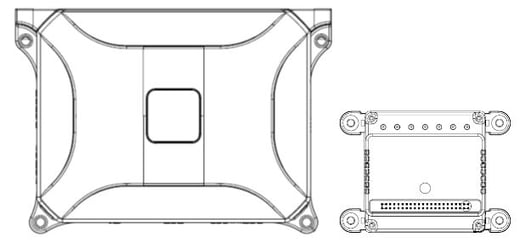
Figure 6: Reduction in Size of Representative Older Versus Newer Drive
Such is the pace of progress in electronic controls that drive the motor. In fact, increasingly, when embedded motion controls are used - either motion control ICs or modules such as shown in the figure, the contribution of the electronic motion controls to the weight of the overall system almost becomes negligible.
The following table shows the impact of controls on overall system weight. Even for the 2010 technology drive the impact on system weight is about 10%, and for the 2020 technology this drops to just 1.3%.
|
|
2010 Representative Motion Technology Drive
|
2020 Representative Motion Technology Drive
|
|
Power Output
|
500 W
|
>1,000 W
|
|
Dimensions
|
109 x 76 x 38 mm
|
37 x 37 x 17 mm
|
|
Volume
|
315 cc3
|
23 cc3
|
|
Weight of Drive
|
.265 Kg
|
.033 Kg
|
|
Weight of Motor
|
2.5 Kg
|
2.5 Kg
|
|
% of Total Motion Control System Weight
|
10.6%
|
1.3%
|
Can we switch?
The single most important change driving the remarkable size reduction in electronic motion controls are the performance of digital switching amplifiers, most often MOSFET switches. These ICs, which when first introduced were prone to failure, prone to overheating, and prone to being large, can now switch with 98%+ efficiency, are extremely reliable and have shrunk to remarkable densities.
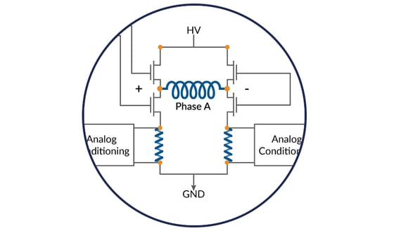
Figure 7: Switching Amplifier
How can a binary switch command a continuously changing output voltage? While it may seem counter intuitive, modern motion control amplifiers do not literally amplify anything. They 'amplify' by entirely connecting, or entirely disconnecting (switching) the motor leg to an HV supply voltage or a GND connection.
PWM (Pulse Width Modulation) schemes ensure that an analog command signal can be represented in this digital all on/all off scheme. For example to present an average of 37.3 volts to a particular motor coil with an HV voltage of 64 volts the PWM output will connect the HV 58.3% of the time (37.3 / 64 = 58.3%), and connect the ground the rest of the time.
Stay calm and switch efficiently
One fairly basic area affected by the drive electronics yet still quite important is the PWM drive frequency. It may be that the PWM drive frequency needs adjusting when changing from a bigger motor drive to a micro-sized motor. Ultimately the optimal PMW frequency is determined by the motor's inductance, but that generally tracks with size.
Smaller motors mean lower inductance. A significant source of chatter and heat generation in small motors occurs when there is too much current ripple coming out of the switching amplifier. In the past, a PWM frequency of 20 kHz may have been typical, but today PWM frequencies of 40 kHz, 80 kHz, or even higher are often needed to correctly control these motors.
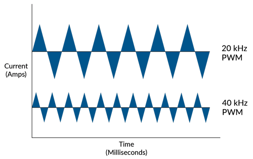
Figure 8: Current Ripple
How does PWM frequency impact heat generation? The answer is that a digital switching amplifier delivers extraneous energy in a saw tooth pattern for a given current command. Increasing the PWM frequency reduces the magnitude of this noise inducing and heat-generating current flow, and improves the accuracy of the current measurement. The figure above shows comparable 20 and 40 kHz current waveforms, although the exact form of the saw tooth will depend on the current command and motor coil inductance.
Increasing the PWM frequency will somewhat decrease your switching amplifier's efficiency, but this is another area that has seen tremendous IC technology progress. MOSFETs in particular have seen big reductions in what are known as 'switching losses' - essentially a fixed loss of energy per switching action. In the past switching losses could eat up 5% or more of the MOSFET's overall efficiency above 40 Khz. With the latest generation of MOSFETs this has dropped dramatically, allowing amplifiers that switch as high as 100 kHz but still operate with 90%+ efficiency.
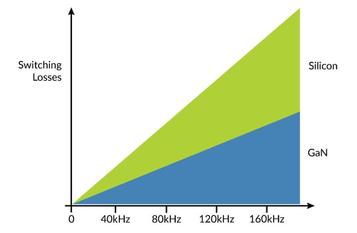
Figure 9: PWM Frequency
An interesting new trend related to this is the slow rise in the use of a new switch semiconductor material, Gallium Nitride, often called GaN for short. Traditional switchers are made from Silicon, but as the figure above shows GaN outperforms Silicon at higher frequencies when it comes to a reduction of switching losses.
While not yet common for use in motion control amplifiers, improvements in the reliability and manufacturing yields of GaN switches over the last ten years means this type of MOSFET is bound to have a growing impact on small motors and low inductance motors that need to switch at high frequencies.
One thermal dagwood sandwich please
Beyond improvements in MOSFET and general IC performance there has been a second, less publicized revolution happening in the area of heat flow management.
Driven by the high volume consumer LED lighting market and the challenge of managing the heat that comes from those tiny packages, a new specialized PCB, known as a metal clad printed circuit board (MCPCB) or sometimes called a thermally conductive PCB, is quickly gaining popularity for motion control amplifiers.
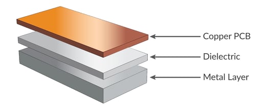
Figure 10: Metal Clad PCB Layers
As Figure 10 shows, this technology stacks a traditional copper PCB which holds the integrated circuits such as MOSFETs, resistors, and capacitors onto a relatively thick metal substrate, usually aluminum or copper. The trick to making this sandwich work is the use of a mechanically rigid dielectric layer which efficiently transfers the heat from the copper PCB to the metal layer.
Prior to the development of this heat management technology, manufactures used a separate step to bond a traditional non heat-conducting PCB to the metal substrate. That approach is more time consuming and not as efficient at transferring heat.
A specific example of how effective such a thermal sandwich can be comes from the PMD laboratory. During one of the many thermal performance tests PMD conducts to certify its amplifier designs, our new N-Series ION Digital Drive, which has a heat sink interface area of about 10 cm2, recorded a temperature drop of only7 deg C from the bottom surface of the above-diagrammed thermal stack to the operating surface of the MOSFET. What makes this remarkable is that these measurements were taken while the amplifier was outputting nearly 2 KWs of power continuously.
Altogether this important new packaging technology has helped accelerate the power density of motion control amplifiers, allowing newer generations of motor and actuator amplifiers to achieve drive output densities of 100W per cc3 and higher.
Why can't I fry an egg on this motor?
To finish up our discussion of advancements in motion controllers that impact small motor operation, we will look at two control techniques, one for Brushless DC motors and one for step motors that improve efficiency, and therefore reduce heat generation in the motor. For motors that may be implanted in the patient are operate by hand, cool operation is vital.
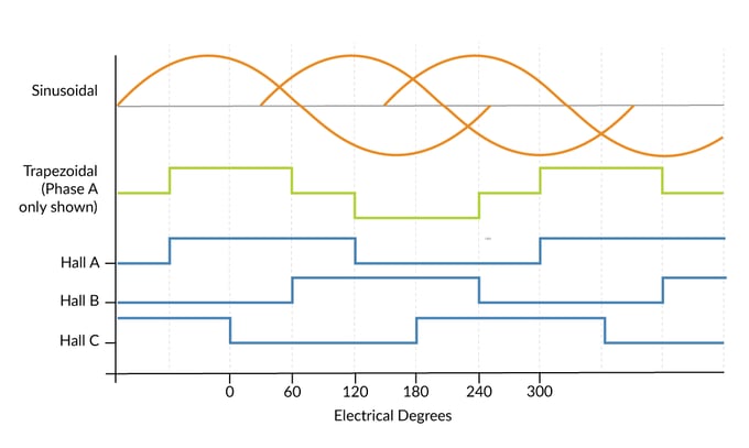
Figure 11: Sinusoidal and Six-step Commutation Waveforms
The first technique to improve efficiency we will look at is FOC (Field Oriented Control) and its close cousin sinusoidal commutation. Both of these techniques apply to Brushless DC motor control and allow these motors to operate more efficiently with more of the commanded voltage creating useable torque.
The traditional approach toward commutating Brushless DC motors is called trapezoidal or six-step commutation. This method relies on Hall sensors which provide a new commutation vector every 60 degrees, which corresponds to six discrete locations per electrical cycle. Both sinusoidal and six-step waveforms are shown above in Figure 11.
In an ideal world however the commutation vector would be at kept exactly 90 deg from the rotor's N-S (north south) vector at all times. The fact that instead, Hall-based controllers receive a new update only every 60 degrees, means the drive vector will be off by up to 30 degrees, and therefore inefficient. This is shown in Figure 12 below where the effective torque output of the motor is reduced in a cyclic pattern by up to 13%. Averaged over a complete rotation the average loss of efficiency is 5%.
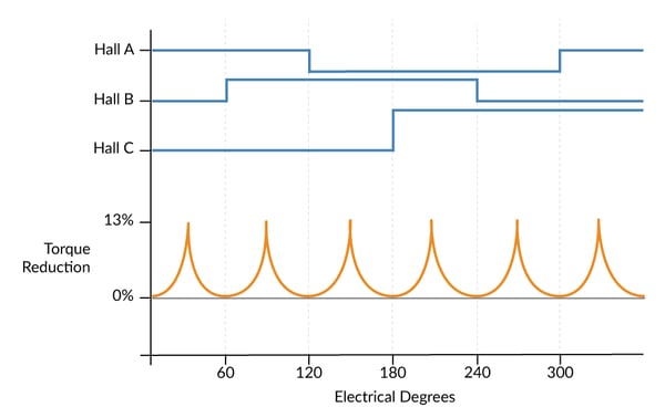
Figure 12: Torque Reduction Using Six-step Commutation
If instead of Hall sensors encoder are used for feedback, which usually provides dozens or even hundreds of position updates per electrical cycle, this problem goes away. The motor stator's vector angle can be kept exactly 90 degrees from the N-S vector regardless of the rotor location, resulting in improved smoothness and efficiency.
You may also be interested in: Field Oriented Control (FOC) – A Deep Dive
Bring on the closed loop stepper
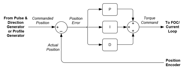
Figure 13: Closed Loop Stepper Operation
The second control technique we will spotlight applies to step motors. This new type of control technique is called closed loop stepper, also sometimes called stepper servo. What makes closed loop stepper powerful is that it can use a standard step motor yet extract more effective torque out of it, particularly over the full range of operating speeds.
How does closed loop stepper work? Closed loop step motor operation is different in three key ways from traditional open loop step motor operation. The first is that it requires an encoder to be attached to the step motor, one with a fairly high resolution. For standard 1.8 degree step motors you will want an encoder with no less than 2,500 counts per mechanical rotation.
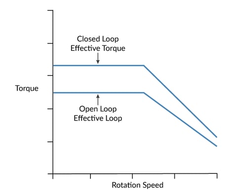
Figure 14: Closed Loop vs Open Loop Step Motor Torque Generation
The second difference is that closed loop stepper operates the motor like a two-phase Brushless DC motor and commutates the phase angle using the actual encoder position. The third difference is that rather than being constant, the height and sign of the current waveform are continuously adjusted based on the output of a position PID (Proportional, Integral, Derivative) loop.
This means closed loop stepper drives the step motor with just enough power to get the job done. Open loop step systems must drive the motor at a power level to handle the worst-case profile and load scenario. The result is that closed loop stepper can drive the motor with much less heat generated.
As mentioned earlier in the article, small step motors benefit particularly from the closed loop stepper control method. Since the encoder determines the position, small variations in the teeth spacing which would otherwise result in bumps and wiggles of the motion, are handled 'invisibly' by the servo, which increases or decreases the applied torque to compensate.
You may also be interested in: New Control Technique Combines Servo Performance With Step Motor Cost
This is similar to the experience that many users have had with regular DC Brush or Brushless DC motors. A well-tuned servo can do a remarkable job of masking small problems with the motor bearing, the gear head, and even the load itself. This is in fact the basis of most machine monitoring observers, and the related art and science of machine failure prediction.
By looking at how the PID's servo error and servo error integral buildup change over time, a lot can be learned about the health of the downstream mechanical components, even if the motor is staying within its servo accuracy target spec and functioning acceptably. Machine failure prediction is a fascinating subject area which is receiving more and more attention and which we will look at in a future article.
Sign Up! Click here to sign up to be alerted when this article is available.
Architecture, architecture, architecture
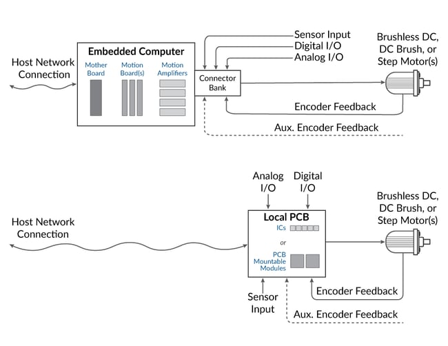
Figure 15: Remote Versus Local Control
Figure 15 shows two approaches to achieving a motion controller function. In one, motors and sensors are located at the target machine while the motion controller and amplifier are located remotely, perhaps in a rack, or perhaps in the form of a motion control board mounted in an industrial computer
The second shows everything hosted locally - the motor, the sensors, and the entire motion controller. When hosted locally, the motion controller can take the form of cable connected modules, an application specific control board built from PCB-mounted modules, or an application specific control board built from an assemblage of ICs.
As it turns out, just as 'smaller is better' for an increasing number of applications when it comes to the motor and amplifier size, 'closer is better' when building machines that use motion control particularly those that integrate analog sensors such as sin/cos encoders.
The reason boils down to two simple principles: shorter signal runs mean cleaner more accurate signals, and shorter signal runs means the servo loop can run faster while still maintaining safe phase margins. Both of these factors have a major impact motion performance, but in particular on positioning accuracy.
While some machine applications will not see big performance improvements from shorter signal runs, systems with smaller motors, and systems utilizing newer generations of encoders such as sin/cos encoders striving for ultra-high accuracy measured in nanometers or even picometers will. Similarly, for spindles that need to maintain high position or velocity control accuracy, fast servo loops and clean sensor signals can make a big difference.
Embedded we stand
The above principle of 'closer is better' explains a slow but distinct trend toward embedded motion control solutions versus remotely mounted solutions. This trend is most noticeable for smaller machines, but can be observed even for larger machines such as commonly used with semiconductor capital equipment, laboratory equipment, and packaging equipment.
While there may not be a big motion performance gain with embedded control in these 'bigger' applications, a single PCB-based embedded motion solution located right at the machine makes the final solution more compact relative to a machine with a control setup that uses cable bundles emerging from the machine connecting to a remote mounted control rack or industrial computer.
Cost-wise, embedded control can be cheaper than module or board based control but this is volume dependent. If the local PCB is designed at the IC level the upfront design effort is usually greater, but if there is enough volume this will be amortized over the larger number of machines and the per system cost may well be lower.
There is a new motion control device however that is easing the barrier to building application specific embedded control boards. Known variously as an intelligent amplifier, programmable amplifier, or motion control module, these PCB-mountable devices greatly simplify the task of creating a custom control board.
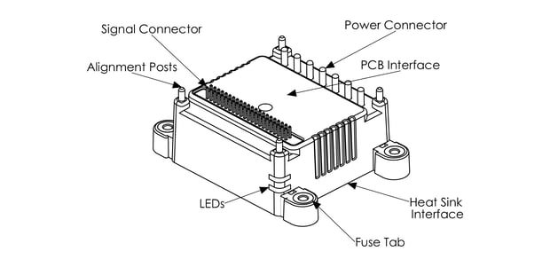
Figure 16: Representative All-in-one Motion Control Module
This is because these devices do all the heavy lifting associated with the machine control function. They can run user application code, generate motion profiles, handle servo positioning, and drive the motor with an on-board amplifier. These devices also offer multiple interfaces, typically serial, CAN, and Ethernet. Most importantly they are small, often measuring just 3-5 cms on a side. Figure 16 shows a representative example of such a PCB-mounted motion control module device.
For the design engineer building an application specific motion control board using these plug-and-play devices, the task is more one of interconnecting then of actual circuit design. Whereas a full blown motion board designed from ICs would typically require a 10+ layer PCB and serious digital and analog design skills, a board made with these plug-and-play motion control modules is typically a 2 or at most 4 layer board, and the design task focusses on selecting connectors and specifying the board's form factor.
While not new, PCB-mounted motion control modules have shrunk dramatically in size and increased dramatically in power output over the last ten years. They are very much a product of the type of electronic advancements discussed earlier. Owing to their tremendous convenience we can safely say that these devices are here to stay and will continue to shrink in size and expand in capability in the future.
Wire we still here?
To wrap up our discussion of the importance of architecture in the machine controller design we look at the impact of architecture on wiring.
Figure 17 shows a centralized/remote and a distributed/local architected six axis control system. Even if both systems use state-of-the art motion controls, the connection architecture will have an impact on the weight of the system due to the difference in wiring.
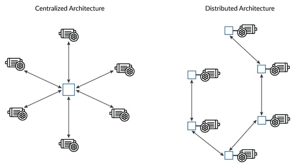
Figure 17: Centralized and Distributed Architecture
A simple example illustrates. Here is an accounting of the wires needed to support a centralized control scheme servicing six motors located in a circle with a radius of .31 m (12") from the center, versus a distributed system servicing the same arrangement. We will assume 3-phase Brushless DC motors along with a Case/Shield wire resulting in the use of four heavier (14 AWG) motor connections per axis, and ten lighter (24 AWG) sensor/ signal wires per axis.
In the distributed system, each drive is assumed to be located at or near the motor and serviced with a two-wire (14-AWG) HV power and a 6-wire (28 AWG) network connection. All other wires such as the heavier connections to the motor coils and the lighter wires to the motor's sensors are assumed to be local and 2" in length.
|
|
Centralized
|
Distributed
|
||
|
|
AWG, Total Length
|
Weight
|
AWG, Total Length
|
Weight
|
|
HV DC Bus Power connections
(2 wires): |
N/A
|
N/A
|
14 AWG, 3.2 m
|
.071 Kg
|
|
CANbus Host Network Connection (6 wires):
|
N/A
|
N/A
|
28 AWG, 9.6 m
|
.011 Kg
|
|
Motor drive connections (4 wires per axis):
|
14 AWG, 7.3 m
|
.163 Kg
|
14 AWG, 1.1 m
|
.027 Kg
|
|
Encoder and other signal connections (10 wires per axis):
|
24 AWG, 18.3 m
|
.041 Kg
|
24 AWG, 3.0 m
|
.007 Kg
|
|
Total Weight:
|
|
.204 Kg
|
|
.116 Kg
|
|
Difference:
|
|
|
|
-.088 Kg
|
This example calculation demonstrates two things: for many systems, the weight of the wiring will exceed the weight of the controls, and a distributed architecture may reduce the weight of the wiring by up to half compared to a centralized system. Nevertheless, as this example also shows the weight of the wiring is just a fraction of the weight of the motor, perhaps 5 to 10% for a typical machine.
Summary
Mobile and portable motion applications are exploding in popularity due to the demands of patient treatment devices, mobile robotics, drones, and a wide range of devices that use motion control and operate 'on the go'.
Smaller motors have made meaningful improvements in the areas of power to weight and torque to weight output. Most noticeably, the closed loop step motor is spawning what is essentially a fourth positioning motor type after DC Brush, Brushless DC, and traditionally controlled step motors.
Motion control electronics have progressed remarkably over the last twenty years, dropping in size and weight by an order of magnitude or more. In addition these new controls easily have the power to run new control techniques that can optimize efficiency and minimize heat generation including FOC (Field Oriented Control), closer loop stepper, and PWM frequency optimization.
Finally, perhaps the biggest impact of increasingly miniaturized controls is that it allows the machine architecture to be re-organized. Moving from centralized motion to local/embedded motion brings advantages of greater signal integrity, faster servo loops, less EMI, increased reliability, and lower cost.
PMD Motion Control Products That Support Small And Ultra Small Motors
PMD has been producing ICs that provide advanced motion control of DC Brush and Brushless DC motors for more than twenty-five years. Since that time, we have also embedded these ICs into plug and play modules and boards. While different in packaging, all of these products are controlled by C-Motion, PMD's easy to use motion control language and are ideal for use in medical, laboratory, semiconductor, robotic, and industrial motion control applications.
MC58113 Motion Control IC
Performance Motion Devices’ MC58113 Motion Control IC is ideal for controlling small Brushless DC, DC Brush, and step motors, providing high-performance motion control features including field oriented control and closed loop stepper operation. In addition, the MC58113 IC provides profile generation, servo-loop closure, commutation, current control, and direct PWM (Pulse Width Modulation) motor output command to drive MOSFET switching amplifiers. It is ideally suited for portable and mobile medical, scientific, robotic, and automation applications and is available as a single, one-axis IC.
Learn more >>

Juno Velocity & Torque Control ICs
Juno Motion Control ICs are perfect for building your own control board and achieving the smallest, lightest per axis control. They feature the latest in servo motor control techniques including PID with feedforward, biquad filtering, current control with FOC, and PWM (Pulse Width Modulation) at up to 120 kHz. Juno ICs represent PMD's latest generation of high performance, low cost velocity & torque control ICs.
Learn more >>
ION/CME N-Series Digital Drives
N-Series ION Digital Drives combine a single axis Magellan IC and an ultra-efficient digital amplifier into an ultra compact PCB-mountable package. In addition to advanced servo and step motor control, N-Series IONs provide S-curve point to point moves and plenty of general purpose digital and analog I/O. With these all-in-one devices building a fully custom board is snap, requiring you to create just a simple 2 or 4-layer interconnect board to connect multiple N-Series IONs together.
Learn more >>
You may also be interested in:
- Precision Fluid Handling: It's All In The Pump
- Precision Fluid Handling: Taking Lab Automation To The Next Level
- Advanced Motion Control of Servo and Step Motors
- S-Curve Motion Profiles - Vital For Optimizing Machine Performance
- Improving Liquid Handling Pumping Through Optimized Feedback
- Syndicated by Robotics Tomorrow