Introduction
In this paper, we will look at four important trends in motion control technology for applications involving medical and laboratory equipment. These applications include automated devices used during surgery, for patient treatment, for patient imaging, and the wide variety of machines that operate in the laboratory such as blood analyzers, DNA sequencers, chemical and biological assayers, and more.
Underlying all four trends are rapid and radical changes in the cost of computing power and amplifier electronics, so much so that the era of motion control technology we have now arrived at could be called the post miniaturization, post specification era.
By this we mean that the electronics have gotten so small and are capable of driving such high currents that the motion control electronics now seldom limit the controller package size. Rather, the size is more often limited by connectors and the practical limitations of servicing controllers once they are installed in the machine.
By post specification era we mean that motion controllers and motor amplifiers now routinely provide servo loops rates, PWM (Pulse Width Modulation) frequencies, and current control frequencies so high that due to the physical limits of motors, improving these specs further would result in a diminishing, if not vanishing, improvement in performance.
So what comes next in a world where the motion control electronics are as small, and the controllers as fast as they can meaningfully become? That is what we will explore in this article, focusing on four motion control technologies that take us beyond raw performance and deliver real and meaningful new capabilities that designers of medical and laboratory machinery can utilize in their next generation designs.
Four Motion Control Trends for Medical Equipment Design:
1) New Encoder Technologies Are Proliferating
The old standby quadrature encoder has been joined by a host of new position sensing technologies and data transmission formats, providing medical machine manufacturers with new package and controller options
For positioning motion control applications, one feedback device, the incremental optical encoder with quadrature output, has been the king of the hill for a long time. With low cost and 'good-enough' resolution, this encoder dominates today's motion control marketplace by unit volume. But in the last ten years, there has been an explosion of new encoder sensing technologies along with, equally importantly, new methods to send that position data to the motion controller.
The basics of sensing position begin with the motors and mechanisms that will be measured. Broadly speaking, position sensors come in rotary or linear configurations, reflecting the two major types of motor actuators, rotary and linear.

Figure 1: Incremental Rotary Optical Encoder
Figure 1 diagrams a basic rotary optical encoder that outputs position information in quadrature format using two wires, called A, and B, and also provides a once-per-rotation Index pulse, called I or Index. An Index pulse provides a brief output signal once every rotation of the motor. This signal can be used during homing, or for automatic count loss correction.
In most quadrature encoders, the A, B, and Index signals are differentially driven to reduce the chance of losing counts through extraneous electrical noise. But this is far from foolproof, particularly in harsh environments with industrial equipment.
Absolutely I Use Absolute Encoders
In addition to potential count loss during movement, the other implication of an incremental system is that the encoder does not know where it is upon wake-up. For many systems, this is easily corrected with a homing sequence executed during startup, but for other applications, it's necessary to know where you are at all times.
This brings us to the second major category of position encoders, absolute position encoders, of which optical absolute position sensors are the most common. As the name implies, these encoders know where they are at all times. For rotary motors, they come in single turn or multi-turn versions, and the output digital word is in binary format, or an alternate format especially adapted for encoders called Gray Coding.
Historically, absolute encoders had thick wire bundles to carry 14, 16, 18 or more bits of position information. Increasingly though, absolute encoders use serial formats such as BiSS or SSI (Synchronous Serial Interface) to reduce the load of wires required to communicate position to the motion controller. We will discuss various types of serial data formats for encoders a bit further in the article.
I Want To Stick To Being Different
Beyond the optical incremental and absolute encoders, there is an ever-expanding array of innovative techniques to provide higher resolution position at a lower cost. In addition to optical sensing techniques, magnetic sensing is increasingly popular, and some encoders utilize capacitive sensing.
Magnetic Encoders use a galvanomagnetic or magneto resistor sensing element and typically output in quadrature format. Earlier models of this technology tended to have resolutions similar to low end optical quadrature encoders, but this has been changing rapidly as the technology matures, and higher resolution units are now readily available.
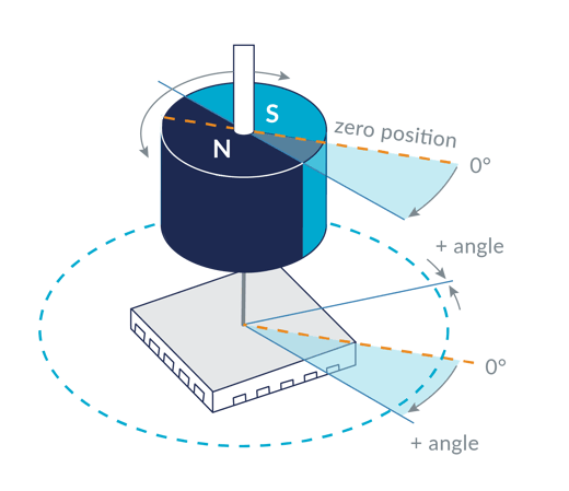
Figure 2: Magnetic Encoder Sensing Element Integrated Directly Onto PCB
The big advantage of magnetic encoders is that the sensor and the encoding disk/surface are contactless, and can therefore be completely sealed, leading to a tolerance to dirt and other interference. Another big advantage is that the alignment of the encoding surface and the sensing element is relatively non-critical. This opens up the possibility of integrating the sensing element directly onto the motion controller PCB (Printed Circuit Board), which in turn allows for new and very compact packaging options. This is shown in Figure 2 above.
Another fast-rising encoder technology is the so-called Sin/Cos Encoder, output waveforms for which are shown in Figure 3. Essentially an encoding variation on the standard A, B quadrature encoding scheme, Sin/Cos encoders output sinusoidally varying A and B signals rather than binary A and B outputs. These sinusoidal outputs are then electronically extrapolated for more position information. Depending on the quality of the signals, a resolution extension of 16 x all the way up to 1,000 x is now achievable.
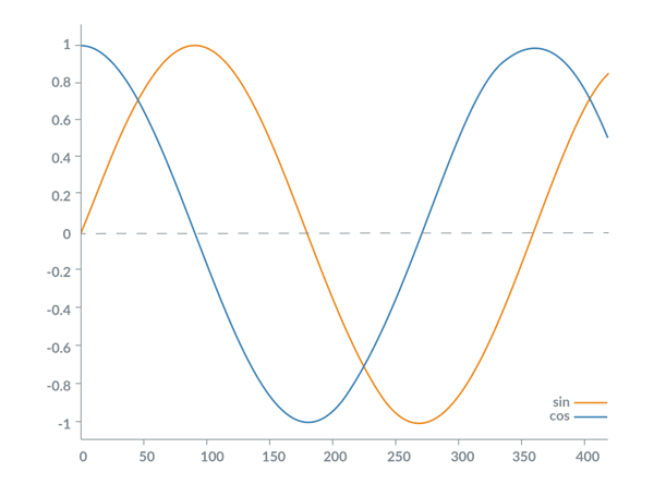
Figure 3: Sin/Cos Encoder Output Waveforms
The reason Sin/Cos encoders have become so popular, especially for high resolution linear applications such as XYZ stages, is that they enable resolutions of 1 nanometer or better, and yet are low in cost. Because they require a minimum of extra electronics in the sensor, and because they present a simple controller-friendly interface consisting of four differentially encoded analog signals (sin+, sin-, cos+, and cos-), they are cost effective to implement both in the sensor and the controller.
One If By Land, Two if By Digital Serial Interface
As motion control for medical applications has become more size and weight sensitive, high speed serial and network-based encoder data formats have gained popularity. For high-end absolute encoders, which have evolved from providing 16 bits, to 20, to 24 bits and beyond, serial networks are a defacto standard because the parallel wire approach for parallel encoders is simply too unwieldy.
The most common standard for a digital serial encoder data networks is SSI (Synchronous Serial Interface) and its big brother BiSS (Bidirectional Serial Synchronous Interface). At the core, these interfaces use an SPI (Serial Peripheral Interface) connection with two data signals and a clock signal to transmit position data from the encoder to the host controller.
A newer serial network, conceptually similar to SSI but adding some twists such as higher data rates and direct support for Sin/Cos encoders, is the Endat serial interface. Although gaining in popularity, whether or not it will become a widely adopted open standard remains to be seen.
Finally, there is also a large category of encoder formats that reside within various popular machine control networks, such as Profibus, CANOpen, Modbus, Devicenet, and others. If the motion controller is already using one of these networks, then these interfaces are a logical choice for the encoder connection as well. However, as an encoder only interface, probably not.
Summary
For medical device designers the new choices in rotary and linear encoder sensing technology and signal transmission formats have allowed products to become more compact, reliable, rugged, and less expensive. At the present time encoder technology innovation is one of the most active areas of motion control development and this trend seems likely to continue into the future.

Prodigy/CME Machine-Controller
PMD's Prodigy®/CME Machine-Controller boards provide high-performance motion control for medical, scientific, automation, industrial, and robotic applications. These versatile all-in-one controllers support quadrature, Sin/Cos, and SSI encoder formats, and are available in 1, 2, 3, and 4-axis configurations, with support for DC Brush, Brushless DC, and step motors. Prodigy/CME Machine-Controllers have on-board Atlas amplifiers that eliminate the need for external amplifiers.
Learn more >>
2) Motor Torque Control Is Getting Smarter And More Precise
Sometimes getting the most out of your motor means feeding it more information. Advanced current control and torque feedforward schemes are delivering smoother, more efficient, and quieter motion.
Many motion applications require smooth motion and high accuracy, both during and at the end of the move. Even if you are using perfectly optimized PID (Proportional, Integral, Derivative) servo parameters to control position, the compensation loop is never perfect because it must manage the influence of a wide range of forces on the actual mechanical system.
The most obvious source of such forces is the motor axis' load itself. The load has mass which reflects inertial forces back to the servo loop, and to the extent that the motor or downstream mechanical connections have friction and compliance (are not infinitely stiff) these forces also reflect back to the motor and affect servo tracking.
Beyond these external system forces, less has been written about the forces that come from the motor itself, and how advanced control techniques can linearize the motor output over the widest possible range of speeds.
What good thing happens when the motor torque output is perfectly linear? The answer is smoother motion, less noise, and more precise moves.
Go Ahead, Make My Torque
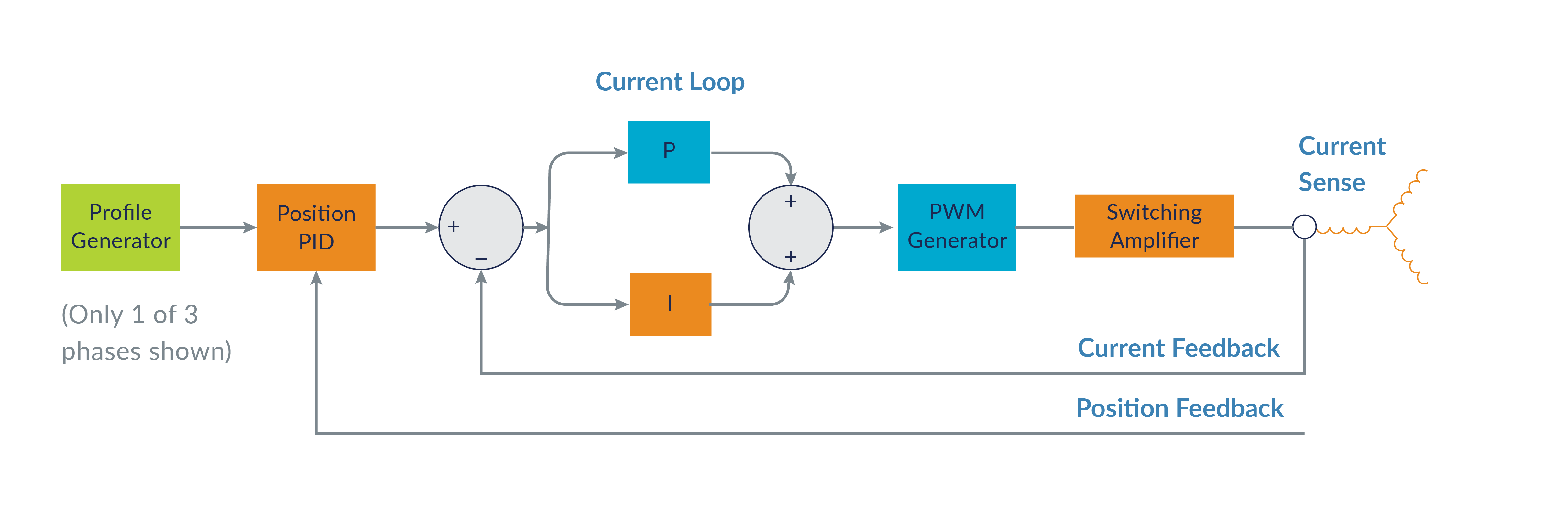
Figure 4: Typical Electronic Motor Control Scheme
Figure 4 shows a typical electronic motor control scheme, with a profile generator, a PID position compensator, a current loop, and a downstream PWM signal generation and switching amplifier. Current flowing through the motor is ultimately what drives the machine axis by generating a torque.
Some simpler control systems dispense with the current loop and directly output a voltage command to the motor, which in turn creates current in the motor coils. As it turns out though, the relationship between the voltage at the motor’s coils and the actual current flowing through the motor can be rather complicated.
The two most important such effects are that if the motor is spinning, the motor will become a generator and develop its own ‘back-EMF’ voltage, and that as current flows through the motor coil, it will tend to resist itself through self-induction. Both effects result in an actual current flow in the coil that may be quite different from the voltage command applied.
So for the majority of motion control applications, a current loop is used which measures and actively controls the motor current. Modern controllers perform this task digitally, using A/D (Analog to Digital) converters. In a DC Brush motor, a single phase current loop is used, while in step motors and especially Brushless DC motors, more complicated multi-phase schemes such as Field-oriented Control (FOC) are used.
These computationally intensive schemes have been in use for a while and are popular because they provide more torque at higher spin rates, and therefore help to linearize the motor's torque output over a wider operating range.
Compensate Me
With a well-chosen current loop in place, even more advanced techniques are possible that utilize information about the motor, or the application, to adjust the commanded current in such a way that the motor torque is more linear.
Why is this necessary? Whether configured as a rotary motor or a linear motor, as we shall see in the discussion below, the physical torque generated by the motor is not necessarily uniform, or even linear. And the machine itself, once it begins to move, is awash in forces not only from the motor but induced by the motion of the machine itself.
Broadly speaking, we will use measured or inferred information about the motor or the load to feedforward a torque into the motor. Our goal is to compensate for machine or motor forces that we know about in advance, thereby reducing the torque command output needed from the PID loop.
The simplest possible kind of torque feedforward is constant bias in the desired torque command to compensate for forces such as gravity. Beyond that but still very straightforward are linear single-axis velocity and acceleration proportional torque feedforward terms, compensating for forces such as friction and inertia.
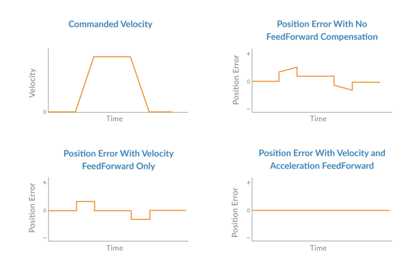
Figure 5: Trapezoidal Motion Profile Position Errors After Velocity and Accel Feedforward
Figure 5 shows an axis moving through a trapezoidal motion profile, and a possible position error response from a well-tuned PID controller. The graph shows the position error with no feedforward compensation, velocity-feedforward applied, and acceleration feedforward applied.
Kinematics We Talk?
Machines that are built with ‘orthogonal’ actuators, such as an X Y stage, have simple reflected forces that are relatively easy to compensate for. Some robot configurations however, such as PUMA-style articulated arms (these are the arms you see welding cars, or moving pallets in factories) have much more complicated reflected torques, and include entirely new forces such as centripetal forces.
A very simple example of forces that can come from non-orthogonal mechanisms is shown in Figure 6, where the gravitational force transmitted to a shoulder joint motor is not constant, but is a function of the position of the shoulder joint.
Figure 6: Non-orthogonal Mechanisms
A machine mechanism that moves and thereby induces reflected torques at its motors is one major category of forces (torques) that can be compensated for electronically. Another major category comes from the motor itself. The reason for this is that motors, whether rotary or linear, do not provide perfect proportional conversion of current flow into generated torque.
One such effect is motor ‘detents’. Detents are felt in a step motor as regular bumps during rotation. With Brushless DC motors detents exist for motors that are not 'slotless'. Similar to step motors, these bumps cause a variation in generated torque even when provided a 'perfect' control waveform.
So how do we correct for detents? The answer is that we can map the torque motion profile of a motor as it goes through an electrical rotation and generate a compensating map of torque values (yet another form of feedforward) to counteract detents or any other systematic non-linearity of the torque . While this compensation technique rarely provides perfect linearization - particularly when motor to motor variation is included. But it can often provide a very meaningful improvement.
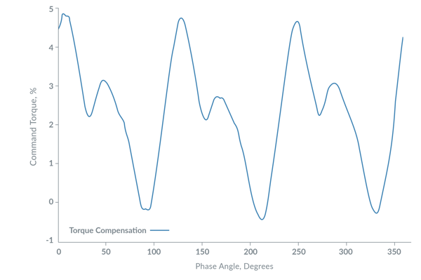
Figure 7: Example Torque Compensation Table Over 360 Deg Electrical Rotation
By way of example, Figure 7 shows a table that was constructed for a Brushless DC motor in the PMD lab. Note that it has a regular repeating pattern within the 360-degree electrical rotation. This is common for motors and relates back to the complicated shape of actual magnetic field interactions between the stator and rotor. For this motor, the total magnitude of the adjustment was no greater than 5%, but for applications that want to go to the 'next level' of smoothness and accuracy, that small adjustment can be important.
It is worth noting that step motors can have their positioning accuracy improved by a similar technique. At a fine resolution, even when presented with a perfect sinusoidal waveform, step motors do not move in exact increments. Small adjustments to the commanded Sin/Cos vector torque lookup table can improve the microstepping accuracy just as was the case for BLDC motors.
You may also be interested in: Motion Kinematics
Summary
Although they take time to set up, for software-based motion controllers these torque adjustment techniques are so computationally efficient that are essentially free. Modern DSPs and dedicated motion control ICs have so much computing power available that they can easily support features such as FOC, velocity and acceleration feedforward terms, and more complex torque compensation mapping.
So to take your machine's performance to the next level, designers of medical machinery should be aware of the trend toward electronic compensation of the motor torque output.

Juno MC73112 Torque Control IC
PMD's MC73112 Torque Control IC provides advanced torque control for Brushless DC motors. Available as a single axis IC, the MC73112 provides four-quadrant motor control, direct quadrature encoder input, field-oriented control (FOC), direct MOSFET switch signal output, and much more. The MC73112 IC is a member of PMD's Juno family of ICs which includes ICs that provide control of DC Brush motors and step motors, and provide high performance velocity control.
Learn more >>
3) Step Motors Learn New Tricks And Solidify Their Spot In Medical Machine Designs
When it comes to step motors, a new drive technique called stepper servo operation is making everything old new again and winning back lab automation designers who may have relegated step motors to the category of low cost but low performance.
Step motors have historically represented a low cost, easy to use positioning control motor option. They do not require an encoder to maintain their position, and unlike DC Brush or Brushless DC motors used for positioning, do not require a servo control loop. Their advantages are low cost, high torque output, and brushless operation. Their main historical drawbacks are vibration, noise, and a limited speed range.
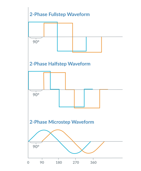
Figure 8: Traditional Step Motor Control Waveforms
Figure 8 shows traditional waveforms for driving a step motor. Step motors are a multi-phase device, meaning multiple motor coils are electrically excited to create motion. Most step motors have two phases but more exotic configurations such as 3-phase or 5-phase also exist.
In the world of step motors, the phasing techniques that the amplifiers employ are given special names such as full step, half step, and microstep control. These different techniques refer to the number of power levels that are applied to each motor coil during an electrical cycle. Whichever drive method is used, the motor moves forward or backwards by altering the electrical phasing. A 'full' step means one 90 electrical degree movement.
Step motors are usually constructed with 1.8 mechanical degrees per full electrical step (90 electrical degrees). So this means a 1.8 degree stepper has 200 full steps per mechanical rotation. In addition to 1.8 degree step motors, 7.2 degree step motors exist as well.
May The Magnetic Force Be With You
With this primer on traditional step motor control behind us, let's discuss stepper servo operation. To understand this new technique though it's useful to get a sense of what's happening inside the motor, and understand in more detail how it generates torque.
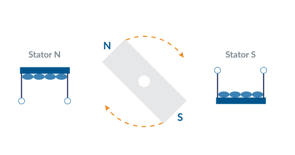
Figure 9: Spinning Bar Magnet Model for Step Motors
When thinking about what creates an electromotive force in a step motor, a spinning bar magnet (the rotor) that interacts with an externally controlled magnetic field (the stator) is a good model to use. This is shown in Figure 9.
When the stator coils are driven with current, a sinusoidal force 'valley' is created which drives the step motor to to settle at a specific position. The more current that is driven through the coils, the greater the height of the force hills and valleys. Wherever the curve is horizontal there is no mechanical torque generated, and wherever the curve is the steepest the torque is the largest.
To create motion, in a traditional step motor control scheme the controller moves this valley forward or backwards based on the commanded position. The motor rotor then 'falls' forward or backwards, maintaining itself at the potential 'bottom' of the force valley in response. Think of a ball settling to the bottom of a trough.
You Had Me At Stepper Servo
Now let's delve into the stepper servo technique, also called closed loop stepper operation. Stepper servo operation is different in two key ways from regular step motor operation.
The first is that it requires an encoder to be attached to the Step motor, one with a fairly high resolution. For standard 1.8 degree step motors, you will want an encoder with no less than 2,000 counts per mechanical rotation, and for 7.2 degree step motors 500 is a bare minimum.
The second difference is that stepper servo operation runs the motor like a Brushless DC motor and commutates the phase angle using the actual encoder position rather than the commanded position. Going back to our force diagram (Figure 9), commutated phasing means the driven phase angle is at the steepest part of the force valley (the point of maximum torque) whereas in traditional step motor operation, the motor is at the bottom of the force valley (the point of zero torque). Figure 10 shows this.
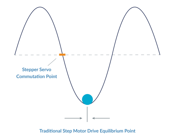
Figure 10: Magnetic Force "Valley" Diagram for Step Motors
What are the advantages of operating a step motor this way? There are many.
One immediate advantage is that losing steps is no longer a concern. Operated as a servo motor the encoder determines the location of the step motor and so the problem of losing steps no longer applies.
A second advantage is that stepper servo operation runs the motor more efficiently, which means less heat is generated in the motor. Commutation-phased motors only output the torque needed to achieve a desired motion profile, while traditionally controlled step motors are driven at a large constant current that must be sufficient to handle the worst case motion requirements.
Another important advantage is that the positioning accuracy of the step motor becomes unlinked from its number of poles or the resolution of the microstepping scheme. In a stepper servo approach the position resolution is determined by the resolution of the encoder, and therefore the same motor could achieve 1,000 or 1,000,000 resolvable location per rotation depending only on the encoder used.
Finally, with the stepper servo technique the motor generates less noise, less vibration, and has better velocity smoothness then with a traditional drive scheme. These benefits stem from the fact that only the amount of current needed is used, and from the fact that the position of the rotor is explicitly controlled rather than being allowed to passively settle to its equilibrium position.
You may also be interested in: New Control Technique Combines Servo Performance With Step Motor Cost
Summary
Because of the need for an encoder, stepper servo is not a good match for basic low-cost motion applications, such as centrifuges and blood analyzers, where a regular step motor will do. But it is starting to make inroads against the Brushless DC motor, which has been the standard choice for high torque brushless actuators. At high speeds of rotation, the Brushless DC motor is still the go-to choice, but at lower speeds below 2-5 kRPM, when high torque in a small package is needed, stepper servo is a formidable new motor drive option.
For designers of medical systems that use motion control, the stepper servo operating mode to control step motors is an important new development in motion control in the last ten years. It is a capability they should be aware of as they design their next generation medical and laboratory machinery.
MC58113 Motion Control IC
Performance Motion Devices’ MC58113 Motion Control IC provides high-performance motion control including stepper servo operation of two-phase step motors. It is ideally suited for medical, scientific, robotics, and automation applications and is available as a single, one-axis IC. The MC58113 IC provides profile generation, servo-loop closure, commutation, current control, and direct PWM (Pulse Width Modulation) motor output command to drive MOSFET switching bridges.
Learn more >>
4) Motion Controllers Will Not Just Control, They Will Also Monitor
Motion controllers already use DSPs (Digital Signal Processor) to execute algorithms to control the motor. A new, future trend is that they will add software that observes and reports on the condition of the motor and the attached mechanics. This opens the door to machine performance monitoring and machine failure prediction.
Compared to the three motion control trends we have just discussed, this fourth trend in motion control technology for medical applications is really a trend that is expected to happen, rather than one that is already happening. With that in mind it's worth remembering the words of Yogi Berra, "It's tough to make predictions, especially about the future.”
The real trend here though is really the historical progression of motion controllers from 'bang bang' transistor-systems written in hardware, to systems that use a microprocessor or DSP to execute software algorithms for the motor control. This trend is long established, having been started in the 1980s, and having fully taken over as the standard paradigm of motion controllers.
But it is only recently that we have arrived at the 'post-specification' era of motion control. That is, where there are few improvements in performance specifications that will have a meaningful impact on the motor performance. So where will we go with the additional computing power, memory, and communication bandwidth that seems to become available to electronics designers with each new generation of microprocessor and PCB packaging technology?
This trend-to-be proposes that the answer is that a monitoring function will be added to the controller's existing control function. If successful, the result will be a machine that can signal its need for preventive maintenance and predict its own failure. This will in turn result in more reliable machines with fewer unexpected failures.

Figure 11: Motion Controller with Monitoring
Have Data Will Travel
The core of the machine monitoring function is data collection, which turns out to be a natural task for software-based motion controllers. Motor controllers, operating at servo rate speeds of 10 Khz or more, continuously measure and adjust the motor drive. It is therefore a simple matter to record into memory useful data such as servo error, drive output, average energy, and much more. In fact, at such high servo rates the challenge is not having enough data, the challenge is summarizing the results so that they can be stored in a reasonable amount of memory.
Which brings us to a second key element required for this trend to occur, data analysis. Analysis here should not be thought of as an absolute one-time result, but as changes in the machine behavior. Predicting that a rotary bearing may fail in the future requires knowing the baseline behavior of that bearing, and then comparing it from time to time to the observed behavior. There are many mathematical techniques that can be applied to this analysis task. A brief summary includes frequency-based math such as FFT (Fast Fourier Transforms), various types of observers, and even simple averaging and long term trending.
Connectivity is the last element required for motion controllers to transition from control only to control and monitoring. Connectivity is crucial because knowing when a motion axis will fail is not helpful if this information cannot be communicated to the outside world. The best candidate right now for handling this communication function is the protocol known as IIoT (Industrial Internet of Things). But there are other options, and this is one area where the technology (and security) may need to evolve a bit before settling on a standard.
In any case, connectivity means the results of data collection and analysis can be reported to plant supervisors and machine manufactures. Just as importantly, connectivity means fleets of operating machines in the field can be compared. Call this meta data analysis - analysis not just of one machine against its own past behavior, but of multiple machines against each other's behavior. Fleet-wide analysis such as this will help to identify patterns with component quality and processes during the manufacturing process.
Summary
As an industry that values reliability and safety above almost anything else, medical and laboratory equipment manufacturers are likely to be early adopters of machine monitoring technology and therefore engineers and systems designers of these machines should be aware of this trend-to-be.
Conclusion
In this article we looked at four motion control technology trends that are already affecting, or will soon affect, medical and laboratory equipment designs.
Is there a larger pattern to these four technical trends? Yes, but you have to pull back the camera pretty far to see it. Each is the direct or indirect consequence of a reduction in the size and cost of computation specifically, and electronics generally, and in the rise of new connection schemes such as SPI (Serial Peripheral Interface) and IIOT (Industrial Internet of Things).
In the future we expect these megatrends to continue, and so machine designers can look forward to further developments in sensors, motor drive techniques, data collection, and analytics that will let them build machines that perform better, are more reliable, and cost less.

You may also be interested in:
- Field Oriented Control (FOC) - A Deep Dive
- Advanced Step Motor Control
- Use Torque FeedForward to Get More From Your Motion Controller
- Motion Controller Design Architectures - A Deep Dive
- Keep Your Step Motor Position with A Closed Loop Motion Control System