This article is the second in a two-part series on precision fluid handling and motion control. In the first installment we build up the fundamentals of liquid handling by looking at commonly used pumping technologies. In the second installment we focus on the higher level systems that utilize liquid pumping such as laboratory automation, patient treatment devices, and scientific equipment.
More and more motion control systems are dedicated to the precise movement of liquids. While pumps and compressors have been around for a long time, two applications have recently become powerful drivers of this technology. The first is laboratory automation - machines used in life science, chemical analysis, and pharmacology. The second is patient fluid processing including dialysis, drug infusion, plasma & platelet extraction, and more.
Pumping liquid in accurate measures is at the core of these systems. For dialysis machines and patient treatment devices such as drug infusers it's the beginning, and the end, of the problem to solve. As we will see in this part II of this series however, for laboratory automation fluid pumping is just one element in a larger system that also incorporates the motion of test tubes, slides, cuvettes, and the various containers that provide and receive the liquid under study.
So, sit back, relax, and pour yourself a glass of your favorite liquid as we take a deep dive into precision fluid handling.
A laboratory in a teapot
Automated laboratory analysis equipment such as blood analyzers, DNA sequencers, and a broad range of other machines that receive, process, analyze and sometimes return submitted samples, come in a variety of shapes and sizes. But at their core many of them share a common architecture. Here are the key elements:
- Sample Entry/Exit Port - This is the mechanical portal where the lab technician loads new samples in, and if appropriate removes processed samples.
- Gantry/Transport - Altogether such a machine functions as a laboratory in miniature, and the gantry is the mechanism that moves samples being processed from one processing station to another. The gantry is most often an XYZ (orthogonal) mechanism, but a SCARA arm on a linear track is an alternative approach for sample transport. Another variation worth mentioning are track systems. Track systems are popular in very large machines, or in systems that must transport samples between two or more gantry-based machines.
- Process Stations - Process stations represent any resource on the machine that will transform or scan samples that are moved to it. Process stations include centrifuges, mixers, and a vast array of devices that transform the samples in some way specific to the end application of the machine.
- Assay/Sensor Stations - Assay stations are process stations that measure one or more characteristics of the samples. Assay stations include microscopes, video cameras, and a wide variety of other chemical, optical, or Xray sensors.
- Storage - Often, after moving through a process station, samples will be moved to a storage area so that a necessary amount of time can pass before further processing can occur, or because the next station in the processing sequence is busy with other samples.
Go ahead, aspirate me a question
In many of the systems described above, a crucial portion of the system is the mechanism which draws in and dispenses fluid. Figure 1 shows a typical approach toward this task. The major elements of this liquid handling system are the pump, the connective tubing, the working fluid, and the aspirate/dispense head (often called the tip).
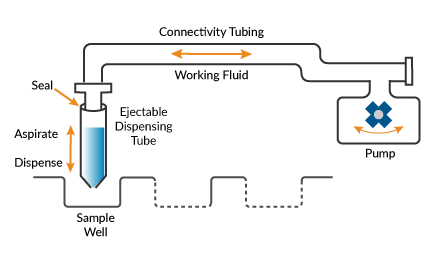
Figure 1: Fluid handling system schematics
Beyond the basics of moving liquid, along the way we need to control the amount of liquid being drawn in or dispensed very accurately, and even more important isolate this liquid sample from previously handled samples to avoid contamination.
How is this done? While the pump does the heavy lifting here, a clever arrangement of what is called the working fluid (often air) ensures that the liquid samples don't get contaminated. When air is drawn into the pump, the suction draws in the fluid from the well. The amount of fluid drawn is always less than the volume of the dispensing tip, ensuring that no sample fluid enters the pump connective tubing. When the pump expels air, the positive pressure pushes the sample fluid out of the tip.
Many liquid handling systems support multiple tips so that liquid can be drawn in and dispensed to more than one port at a time. Some models provide more than 1,000 such ports.
Get a move on!
Are there special motion control techniques that apply to the problem of moving objects that hold liquids? The answer is yes… and no. A big 'yes' stems from the high level of reliability that is needed for such valuable payloads. This is similar to industries such as semiconductor equipment where processed wafers can have a value of $100,000 or more. So, the motion must be very robust and reliable.
Along those lines, in liquid handling automation position encoders are the norm, even when step motors are used, which would otherwise not require an encoder for positioning. Why is this? As the saying goes, 'stuff happens'. There could be a glass shard that finds its way to a mechanism or a long-ago spilled liquid that is slowly degrading a linear slide. Having an encoder on the motor and sometimes also on the load allows such mechanical problems to be detected.
In addition, machines that can move slides, test tubes, or special carriers called microplates (which can hold 1,536 separate liquid samples or more each) tend to be mechanically complex and on the large side, in the range of microwave ovens to full-sized refrigerators.
Whatever their size, the wider the motion range and the heavier the load, the greater the importance of minimizing vibration. Vibration is the enemy of reliability and accuracy. Figure 2 shows a representative mechanism with an actuator (in this case a rotary motor), an end effector, and a mechanism base, all of which may have their own mechanical resonance frequencies.
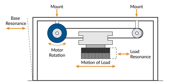
Figure 2: Mechanism with an actuator, end effector, and mechanism base
My kingdom for a Bode plot
So how do we minimize vibration and reduce overshoot and settling time? The answer is by working with nature, or more accurately the laws of physics. As Newton taught us, every action has an equal and opposite reaction, so if the motor drives the end effector with a given force, an equal and opposite force will be injected into the mechanic that supports the end effector.
Both the end effector and the support mechanics tend to have their own resonance points. So, to get a handle on all of this, it's a good idea to perform a resonance scan of the mechanics. The basic idea is to operate the motor in a sinusoidal back and forth motion, sweeping from a low frequency to a high frequency, and observing the response in the mechanics.
Such scans are known as Bode plots. There is more than one type - some characterize the mechanism with no controller active (open loop) and some with the controller active (closed loop). Even if we don't have a sensor located at the load, with the controller active the response of the servo motor (which has an encoder attached to it) will tend to show resonance points in the mechanics because resonances will reflect energy back into the motor.
I think therefore I s-curve
Once we have a sense of the system's dynamics and are ready to optimize controls, the first step is to select motion profiles that minimally excite resonances in the mechanics. How do we do this and what kinds of motion inject the least amount of vibration energy into the mechanics?
In short, the answer to both questions is that we minimize jerk. Change in the rate of acceleration, or jerk, is a primary source of vibrational energy injected into the mechanics. So less is more. As Figure 3 shows, in a trapezoidal move there are three segments; accel, coast, and decel. The change in acceleration at the segment changes is, at least in theory, infinite because the duration of the acceleration transition is zero.
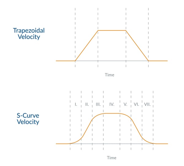 Figure 3: Trapezoidal vs. S-curve profiles
By adding an S-segment, which is an interval over which the acceleration transitions from one value to another, the total vibrational energy as well as the frequency range of injected vibration is reduced.
In a perfect world, you would drive the profile so as to avoid specific resonance frequencies. In practice, trial and error will help you determine what works best. The trick is to add a small amount of "S" so that the total move duration is not unduly lengthened, while still dramatically reducing the induced mechanical vibration.
It is worth noting that the impact of S-curve profiles is not limited to servo motors. Not only do they apply to step motor driven systems, they are actually even more important for step motors. This is because step motors don't have a PID position control loop that gives the designer additional control dimensions to vary. To a large degree the only adjustable variable with step motors is the profile.
Swing low sweet biquad
Once you have your profiles organized, for servo-based control systems there is another general-purpose technique you can use to reduce resonances in large mechanisms such as gantries. Most motion controllers these days offer frequency-domain filtering capability using a biquad filter mechanism. Biquads can be programmed to construct a variety of filter types including low pass, notch, and band pass. Depending on what is happening with your machine's mechanics these filters can be applied to help attenuate specific resonances and linearize the overall system response.
Generally, this kind of application specific filtering is built on the back of a Bode-based system analysis as described earlier. Such a session involves generating open and closed loop Bode plots for one or more axes in your system, from which you should be able to identify resonance points or areas where the phase margin is marginal, resulting in a tendency to oscillate.
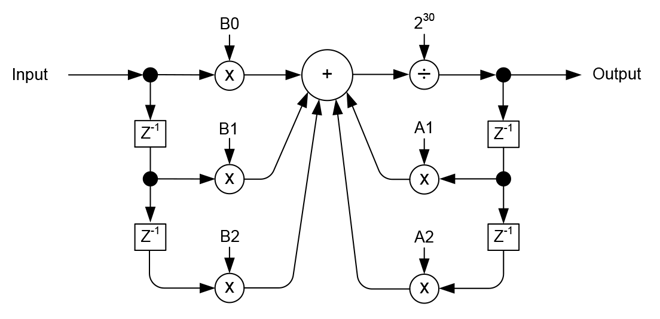
Figure 3: Biquad filter diagram
Despite the seeming mastery of time and space that Bode plots can provide, when fighting a resonance issue in a discrete time sampling system you will inevitably do some manual tinkering of the filter to get the best result. Bode plots and other traditional servo optimization techniques assume an analog system, where input and output values change continuously. Digital systems however adjust their values to the beat of a digital metronome (the sample period) and are therefore not a perfect representation of the real world.
Feed forward me!
With our profiles optimized to minimally inject vibration, we are ready to add another control element that is important for servo-based machines. This control element is feedforward.
Assuming a Cartesian XYZ type motion system, applying feedforward is pretty simple. By the way, if you want to explore non-Cartesian mechanics (which is definitely a bit more of a challenge), check out PMD's deep dive on Motion Kinematics.
In any case, we want to inject an acceleration-proportional signal directly into the position loop that offsets the inertial forces our load and end effector will experience. What forces are these? Once again our friend Newton tells us that objects at rest tend to stay at rest, and objects in motion tend to stay in motion. So, this means during acceleration the load will lag, while coasting the contribution will be zero, and during deceleration, the load will lead.
While it may be possible to calculate the feedforward gain amount, the simplest procedure is to just use trial and error. Here's how you do it: Set up a simple PID loop with no integrator, just a moderate amount of P and D. Now set up your performance trace (motion oscilliscope) software to capture the servo error over the entire move. Start with small accel feedforward values and increase until you notice the servo error is minimized. Don't forget to check out the move forwards and backwards. Some sample capture traces are shown in Figure 4.
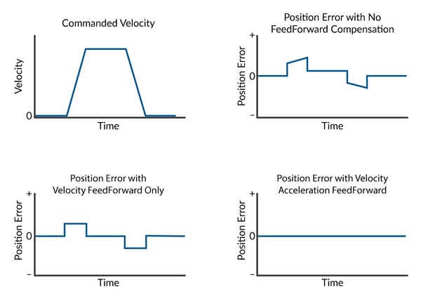 Figure 4: FeedForward
Feedforward terms are 'open loop', so they can not actively adjust for changes in the system such as increased mechanical wear and tear due to aging, or different loads. This means you should pick average values for feedforward gains, and you shouldn't expect perfection in real-world conditions.
What about velocity feedforward? Most motion controllers offer this feature, so if there are velocity-proportional forces in your system, by all means, apply velocity feedforward to compensate.
Finally, if you have a vertical axis under servo control, or if for whatever reason there is a constant directional force on the axis, consider using your motion controller's PID bias setting (sometimes called a motor bias or motor command offset) to feedforward a constant value that counteracts the constant force.
Whatever we can do to simplify the job of the servo loop will make the servo loop easier to tune and improve performance. So, compensating for dynamic or static forces via feedforward is a good idea.
You may also be interested in: Motion Kinematics
I challenge you to a dual loop
There is one more motion control trick in the tool bag that applies particularly to systems with complex and compliant linkages between the drive motor and the load. In such a scenario, despite one's best efforts, the resonances and mechanical inaccuracies from connecting gearheads, linkages, belts, or other couplings may defeat even the best applied resonance reduction techniques.
In this circumstance the most straightforward solution is to reduce the mechanical compliance, for example by going from a motor with a gear head to a direct drive motor. But direct drive motors are expensive, as are other approaches to tightening up the mechanics. Is there a technique that lets me keep my existing mechanism but just lets me position the load more accurately?
The answer is yes, although as the fine print says... individual results may vary. A technique that, at least on paper, allows designers to have their cake and eat it too in these circumstances is called dual loop and is shown in Figure 5. Although there are a few different approaches to dual loops in common use, the one shown in the Figure below is representative.
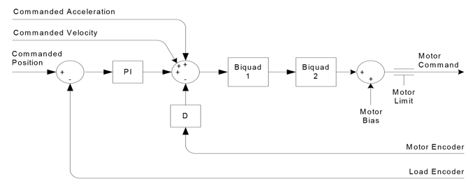
Figure: 5: Common Dual Loop
Here's how it works: Rather than depend on the motor encoder to determine the final position location of the load, in a dual loop arrangement an encoder directly measures the load position. The encoder on the motor no longer has a direct bearing on the commanded load position, and instead is used only to stabilize the servo loop.
Dual loop is a technique that does require more resources, in particular an extra encoder per controlled axis. But it has been used effectively in many applications and despite the extra cost and complexity may be worth looking into.
Summary
Moving liquid, and moving containers that hold liquid, represent two critically important tasks in the fast-paced field of laboratory automation. Such machines make our modern medical, chemical, and pharmaceutical worlds possible and are an increasingly important user of motion control technology.
The key to designing a liquid handling system is to understanding what type of fluid pump will work best in your motion control application, and selecting motion controls that give you the level of fluid pumping performance you need.
The key to integrating these liquid pump controllers into a complete laboratory analysis machine is characterizing the mechanical behavior of the machine and applying motion control techniques such as s-curve profiles, biquad filters, feedforward, and dual loop control to maximize throughput and minimize load ringing and settling time.
PMD Products Used In Laboratory Automation And Scientific Instruments
Performance Motion Devices has been producing motion control ICs that provide advanced position and torque control of step motor, DC Brush, and Brushless DC motors for more than twenty-five years. Since that time, we have also embedded these ICs into plug and play modules and boards. While different in packaging, all of these products are controlled by C-Motion, PMD's easy to use motion control language and are ideal for use in pick & place machines, laboratory equipment, liquid handling, and a wide variety of other high performance motion control applications.
Multi-axis Positioning Control ICs
Magellan Multi-Axis Motion Control ICs are perfect for building your lab automation control board from the ground up. Magellan ICs feature the latest in profile generation, servo loop closure, current control, dual loop control, profile synchronization, event management, and PWM (Pulse Width Modulation) signal generation. Leverage our twenty years of experience and extensive application examples to bring your next motion design project to life using Magellan Motion Control ICs.
Learn more >>
Step Motor Control Solutions
PMD provides a wide assortment of motion control ICs that provide advanced microstepping and closed loop control for step motors. Our MC54113 IC is part of the Magellan IC family and provides profile generation, current control, stall detection, and performance trace & optimization for step motors. Our MC74113 and MC75113 ICs from the Juno family input pulse and direction signals and deliver ultra-quiet, ultra-smooth microstepping control. Discover why PMD is the world-wide leader in high performance step motor control integrated circuits.
Learn more >>
Prodigy/CME Machine Controller
PMD's Prodigy®/CME Machine Controller boards provide high-performance motion control for medical, scientific, automation, industrial, and robotic applications. These versatile all-in-one controllers support quadrature AB, Sin/Cos, and SSI encoder formats, and are available in 1, 2, 3, and 4-axis configurations. Providing support for DC Brush, Brushless DC, and step motors, Prodigy/CME Machine Controllers have on-board Atlas amplifiers that eliminate the need for external amplifiers. Want to get your next laboratory automation design project up and running quickly? Put a Prodigy/CME Machine Controller board on the job.
Learn more >>
ION Digital Drives
ION Digital Drives combine a single axis MC58113 IC and a high power digital amplifier into a compact rugged package. Whether used for S-curve point to point moves, high speed centrifuge control, or advanced process stations control applications, IONs are easy to use plug and play devices that will get your application up and running in a snap.
Learn more >>

In Case You Missed It!
Read Part 1, Precision Fluid Handling: It's All In The Pump, get an understanding of what type of fluid pumps will work best in your motion control application, and what type of motion control techniques will give you the fluid pumping accuracy that you need..
Read Paper
Related papers and resources:
- Precision Fluid Handling: It's All In The Pump
- Motion Control Techniques for Improved Liquid Handling
- Motion Control Technology Trends for Medical and Laboratory Applications
- Improve Liquid Handling Robot Throughout with Direct Path Planning
- Optimize A Control Architecture for High Accuracy Syringe Dispensing