Everyone working in motion control has a war story; be it the machine that stopped working mysteriously or the motor that wouldn't stop vibrating. This deep dive around servo motor noise is part of a series that focuses on motion control problems you may run into and provides some ammunition to fight the good battle and get your machine design and development project back on track!
My servo motor is making a lot of noise
A noisy or chattering servo axis is perhaps the single most common motion problem that engineers encounter when building their DC Brush or Brushless DC motor-based machine. This is not only annoying but can cause increased wear and tear on the motor and downstream mechanisms. The problem can occur both when the servo motor is holding position, and when it is moving - although the sound characteristic may be different for each of these conditions.
As it turns out, this common motion problem can come from a number of areas, and therefore can have a number of solutions, so let’s get started!
Give your PID a tune up
The behavior of systems that use a servo loop to control the motor position are dominated by the settings of the tuning parameters. Most engineers use the ever-popular PID (proportional, integral, derivative) loop to control their system, and much has been written about how to tune PIDs, including some articles by Performance Motion Devices (PMD). The Figure below shows the control flow for a typical position PID loop.
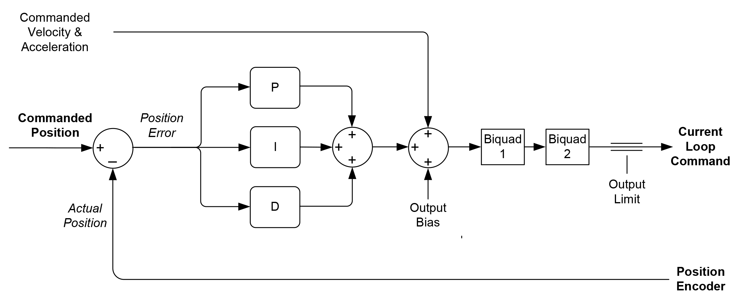
Figure 1: PID position loop control flow
Increasingly, engineers use auto-tuning software to determine their PID parameters. You can use an auto-tuner either to generate final parameters, or better yet to generate a set of starting values which you then further tweak and optimize.
A full treatise on servo loop tuning is beyond the scope of this article, but there are two quick tuning characteristics you can confirm to make sure your system is at least in the ball park. The first is to check that your axis is critically damped, rather than overdamped or underdamped.
While there are precise mathematical definitions for these terms, the main thing is to familiarize yourself with the general form of the response that you want (critically damped), and adjust your settings if what you see is clearly one of the forms you don't want (underdamped or overdamped).
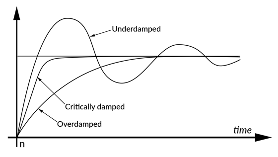
Figure 2: Underdamped, critically damped, and overdamped response curves
Note that the curves above are generated using a step function trajectory profile. The axis is asked to instantaneously jump forward or backward a small distance, and the resultant response of the actual motor position is then plotted. Nearly all motion system vendors provide a step function profiling capability as part of their tuning control software.
If you have the ability to generate Bode plots on your system, then you should also focus on two other measures of control system stability; phase margin and gain margin. Most systems will want to have a phase margin of 40 deg or higher, and a gain margin of 10 dB or higher. The more borderline the control loop stability is, the more the system will tend to oscillate and generate noise as it moves or even as it just holds position. So a system that has good stability characteristics is a strong foundation for a motion system that runs quietly.
Lower your derivative term
If using a PID controller, a high value for the derivative term tends to make the motor chatter and, in the extreme case, sound like a bag of ball bearings. Try lowering your derivative term in combination with your proportional gain to reduce noise.
If the noise goes away but the performance is no longer where you want it to be, perhaps because the system has now become underdamped, consider operating with two sets of servo parameters, an active set and a holding set. Many applications are fine with a bit of noise during motion but need to be quiet while holding position. Using a less aggressive, quieter holding set may be a good solution since the servo usually doesn't have to do much work to hold the axis in the same position.
Try a different sampling time
Another servo-related area to look at is the loop speed. Digital servo systems tend to run at very high servo loop rates, much of which is not needed in the average application. Higher servo loop rates can excite more resonances in the system's frequency response curve.
So, investigate whether changing the servo loop time, or the derivative sampling time if it can be adjusted, helps with audible noise. When lowering the servo loop rate, make sure you re-tune your PID parameters. While the P (Proportional) term may or may not be affected, the I (Integral) and the D (Derivative) values definitely will since they are time dependent.
Bail your system out with a biquad
There are a few general-purpose filtering techniques that you can try to better stabilize the control loop, which should help to lower noise both at zero velocity and while moving. Most systems that offer such a frequency-domain filtering capability use a biquad filter mechanism because it is flexible and programmable.
Biquads can be programmed to construct a variety of filter types including low pass, notch, and band pass. Depending on what is happening with your machine's mechanics these filters can help attenuate specific resonances and linearize the overall system response.
Generally, this kind of application specific filtering is built on the back of a system analysis session. Such a session involves generating open and closed loop Bode plots for one or more axes in your system, from which you should be able to identify resonance points or areas where the phase margin is marginal, resulting in a tendency to oscillate.
While not for the faint of heart, mechanical/control systems analysis such as this has become a lot easier in the last several years as motion control vendors include sophisticated tuning and analysis tools with their controller's exerciser software offering.
You may also be interested in: Mechanical Resonant Frequency and How to Analyze It
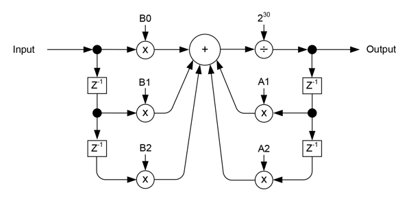
Figure 3: Biquad filter diagram
Despite the seeming mastery of time and space that Bode plots can provide, when fighting a noise issue in a discrete time sampling system you will inevitably do some manual tinkering of the filter to get the best result.
Bode plots and other traditional servo optimization techniques assume an analog system, where input and output values change continuously. Digital systems however adjust their values to the beat of a digital metronome (the sample period) and are therefore not a perfect representation of the real world. So, more often than not trial and error will be an important part of reducing or eliminating a persistent noise challenge.
Is there a deadband in your future?
A special type of filter that can be quite effective at reducing noise is called a deadband filter. Used in either the current loop to limit integral, or the position loop, this technique tells the servo loop not to worry about small amounts of windup, or small amounts of position error, and to only kick in for larger corrections. This has the effect of reducing the number of small corrective commands, thereby reducing noise.
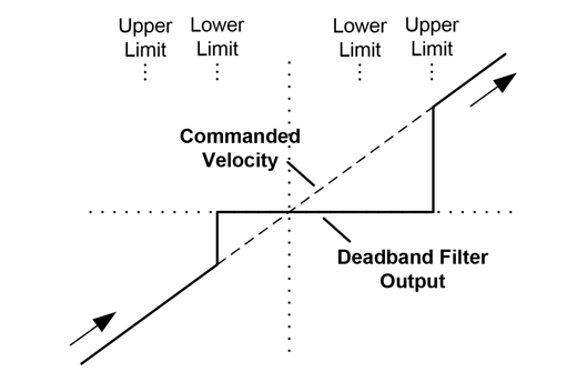
Figure 4: Deadband filter diagram
Figure 4 shows a general-purpose response curve for a deadband filter, which utilizes programmable lower and upper limits to establish the engage and disengage points of the filter hysteresis. If you end up using a deadband filter in your control system, make sure you test it out over the range of loads and operating conditions your system will experience. You want to ensure that the applied values achieve the desired effect over the full projected lifetime and application space of the machine you are designing.
Curb your current loop
If in your quest to lower noise, you have fully dissected the position servo loop but still have issues, it may be time to look at the amplifier and its current loop. A current loop inputs the desired motor current and controls the voltage to the motor while measuring the actual current in the motor leg. The goal of the current loop is to make the actual current in the motor follow as closely as possible the commanded current from the upstream position loop (or sometimes velocity loop).
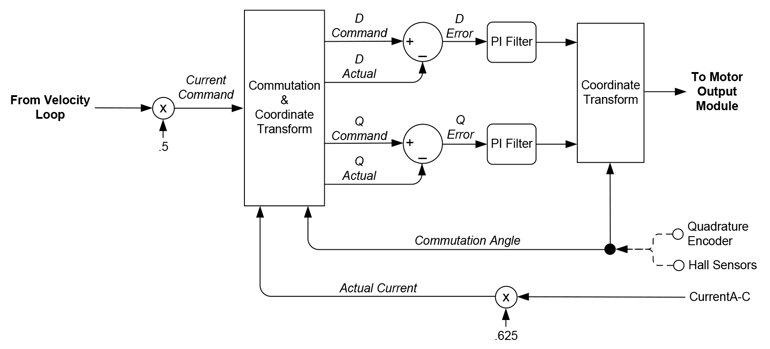
Figure 5: Example current loop and FOC (Field Oriented Control) commutation control flow
For starters, sometimes noise is generated from an overly aggressive current loop. The current loop is where the electromagnetic rubber hits the road, and large spikes in the voltage sent to the motor can cause the motor to act like a speaker. Linear motors seem to be particularly sensitive to this, perhaps because their mechanical layout resembles a sounding board!
So, if you are using a digital amplifier, try lowering the current loop gains, or re-running the auto-tuner with a less aggressive setting if that level of control is available.
If unsure, a quick check that can confirm an overactive current loop diagnosis is to turn off the current loop by running the amplifier in voltage mode. Not all amplifiers allow this option, and if they do, you will probably have to retune the position loop to get comparable overall results because the amplifier gain may be very different with and without current loop enabled.
But if the chatter you are hearing quiets down upon turning off the current loop, you have confirmed that the current loop is an issue. By tweaking the PI (proportional, integral) values of the current loop you can usually reduce the noise while stay maintaining good motor performance.
You may also be interested in: Digital Current Loop Significantly Quiets Step Motor Noise
Increase the PWM frequency
Sometimes the current loop tuning is fine but the PWM (Pulse Width Modulation) frequency is too low for the inductance of the motor being driven. Modern motors seem to be trending towards lower and lower inductances. In the past, a PWM frequency of 20 kHz may have been common for a typical small motor such as a NEMA 23, but with the prevalence of even smaller motor form factors and ultra-high acceleration motors PWM frequencies of 40 kHz, 80 kHz, or even higher are often needed to correctly control the motor.
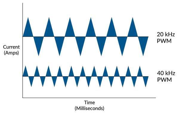
Figure 6: Current ripple
How does PWM frequency impact noise? The answer is that a digital switching amplifier delivers extraneous energy in a saw tooth pattern for a given current command. Increasing the PWM frequency reduces the magnitude of this noise inducing and heat-generating current flow, and improves the accuracy of the current measurement. The figure above shows comparable 20 and 40 kHz current waveforms, although the exact form of the saw tooth will depend on the current command and motor coil inductance.
Of course if you are the rare person using a linear amplifier rather than a digital switching amplifier, none of these comments regarding PWM apply, since those amplifiers use a completely different scheme that does not involve digital on/off switching at a specified frequency.
Note that there is a practical limit to how high the PWM frequency can be set because digital amplifiers lose efficiency the higher the switching speed is set due to a phenomenon called 'switching loss'. Nevertheless, many high-performance motor amplifiers offer selectable switching speeds from 20 kHz to 80 kHz, and amplifiers specializing in driving miniature motors (smaller than NEMA 17) go even higher.
A show of legs
Another area to be aware of is what type of current sense technology your amplifier uses. Fancy amplifiers for three-phase Brushless DC motors and two-phase step motors continually change which phase they measure the current from as the motor rotates. This is pretty straightforward for Hall-based commutation, or for full step motor drive where current flowing through each leg is all positive, zero, or all negative.
But for sinusoidal current waveforms that come with techniques such as FOC (Field Oriented Control), multiple current readings are taken at the same time and then algorithmically stitched together to determine the instantaneous current through each motor coil. The basic wiring scheme is illustrated in Figure 7.
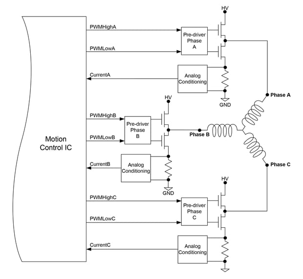
Figure 7: Brushless DC current control sensing diagram
The key to this technique, which is called leg current sensing, is that the current is measured through the bridge's bottom switch which directly connects to ground. Some techniques for measuring the current use phase-based current sensing, which also uses a dropping resistor to sense current, but which float with the motor coil excitation voltage and uses additional circuitry to isolate just the current measurement signal. This is a technique that while simple to implement, tends to have more noise in the measured current.
So if you discover that your amplifier circuitry doesn't use leg current sensing, consider changing amplifier vendors or amplifier types to upgrade to this approach. You should see a benefit in the form of less noise and chatter.
Give your amplifier a wellness check
If none of the above current and amplifier related suggestions solve your noise problem, it may be time to take things to do a wellness check on your amplifier.
Grab a current probe and try this test: Lock the rotor and send a sinusoidal current command to the amplifier. Use the current probe to measure the actual current through each leg of the motor.
Does the measured current look sinusoidal? Are there strange jumps at the zero current crossing? Does the current waveform flatten out (saturate) at the top of the sinusoid? All of these may indicate problems with the current loop, or improper scale settings in the amplifier.
If all else fails but you still suspect the current loop, talk to your motor vendor and see if they can help. They will likely be able to provide suggestions on how to adjust the amplifier, or how to choose an alternative model that generates less noise.
Try sinusoidal commutation or FOC (Field Oriented Control)
Moving past the position servo loop and the amplifier, there are still more issues for you to consider when fighting a noise problem in a servo motor.
Brushless DC motors that are commutated with traditional "6-step" control are susceptible to noise at the Hall sensor boundaries. As the motor rotates, when entering each new Hall state, the current flowing through the coils changes abruptly, injecting a roughly 15% discontinuity in the motor output torque.
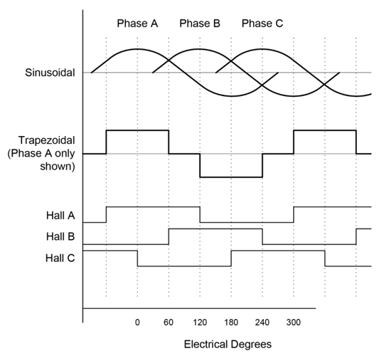
Figure 8: Sinusoidal and trapezoidal commutation signals diagram
If your requested final position happens to fall on such a Hall boundary, the motor may become less stable as the servo controller tries to hold position across this abrupt torque boundary. Servo loops like to have nice, proportional response curves, and the response of the motor at these boundaries is anything but. Utilizing sinusoidal commutation with a position encoder, which has far more resolvable locations than a Hall sensor, solves this problem by advancing the commutation phase angle in very small increments that eliminate big changes in torque.
You may also be interested in: S-curve Motion Profile - Vital for Optimizing Machine Performance
Check out the mechanics
If you have checked out the control system thoroughly, you may find that the mechanical system is too compliant to operate at the performance level you want. Compliance and its binary non-linear cousin mechanical backlash are anathema to stable motion control. They cause the mechanical axes to overshoot and oscillate and inject high-frequency energy into other parts of the mechanics which can cause further oscillations.
One solution for this problem is to replace rotary motors that drive gears and pulleys with a direct drive motor. By simplifying or eliminating mechanical linkages the system gets stiffer, which makes it less apt to oscillate.
But not every application can support the cost of a direct drive motor, so rather than diving all the way into a direct drive motor, it may be that your machine just needs the next level of ball screw quality, a better coupling, more rigid framing, or some weight redistribution.
Summary
We can draw a parallel to the old adage that says if you really want to be an expert on a subject, teach it. Similarly, if you really want to understand your machine, fix it. Hopefully this article has provided some helpful suggestions to do just that.
The moral of the story is that in the end, there is nothing like diagnosing and solving real world problems to expand your knowledge and put you on the road to becoming an expert in the design of machines that use motion control.
PMD Products That Control Servo Motors
PMD has been producing ICs that provide advanced motion control of DC Brush and Brushless DC motors for more than twenty-five years. Since that time, we have also embedded these ICs into plug and play modules and boards. While different in packaging, all of these products are controlled by C-Motion, PMD's easy to use motion control language and are ideal for use in medical, laboratory, semiconductor,robotic, and industrial motion control applications.
Magellan & Juno Motion Control ICs
Magellan and Juno Motion Control ICs are perfect for building your own control board and achieving the lowest cost per axis. They feature the latest in servo motor control techniques including PID with feedforward, biquad filtering, current control with FOC, and PWM (Pulse Width Modulation) at up to 120 kHz. Magellan ICs are PMD's world-leading solution for positioning motion control, while the Juno products represent PMD's latest generation of high performance, low cost velocity & torque control ICs.
Learn more >>
ION Digital Drives
ION Digital Drives combine a single axis Magellan IC and an ultra-efficient digital amplifier into a compact rugged package. In addition to advanced servo motor control, IONs provide S-curve point to point moves, i2T power management, downloadable user code, and a range of safety functions including over current, over voltage, and over temperature detect. IONs are easy to use plug and play devices that will get your application up and running in a snap.
Learn more >>
Prodigy Motion Control Boards
Prodigy Motion Control Boards come in various form factors including PC-104, standalone, and standalone with built in Atlas Amplifiers (Prodigy/CME Machine Controller). In addition to ultra-smooth 7-phase S-curve profiling, these cards provide multi-dimensional synchronized contouring, electronic gearing, and a range of other features to form the core of your next machine design project.
Learn more >>
Pro-Motion Analysis Software
Pro-Motion is PMD's easy-to-use Windows-based exerciser and motion analysis program. It offers ready-to-go capabilities your entire development team will be able to share. A step-by-step axis wizard allows designers to quickly and easily tune position loop, current loop, and field-oriented control motor parameters. Advanced users can access a complete motion analysis package with Bode plot generation and auto-tuning.
Learn more >>
More in this series:
You may also be interested in:
- Mechanical Resonant Frequency and How to Analyze It
- S-Curve Motion Profiles - Vital For Optimizing Machine Performance
- Motion Controller Design Architectures - A Deep Dive
- Improving Liquid Handling Pumping Through Optimized Feedback
- Field Oriented Control (FOC) - A Deep Dive


