
Everyone working in motion control has a war story; be it the machine that stopped working mysteriously or the motor that wouldn't stop vibrating. This deep dive around step motor noise is part of a series that focuses on motion control problems you may run into, and it provides some ammunition to fight the good battle and get your machine design and development project back on track!
My step motor is noisy when it moves
Step motors are a popular motion control choice in positioning applications for two main reasons - their ease of use and their low cost. But step motors have a well-known liability which is that they are noisy and tend to vibrate when moving.
Step motor noise, while annoying, is not a motion control problem in the sense that a mistake was made during the machine design process. Even if you doing everything right applying traditional control techniques, you will get some noise. But importantly, there are control techniques, some quite new, that have dramatically reduced and in some cases eliminated the step motor noise & vibration problem.
So in this entry to PMD's Common Motion Control Problems series, let's break through the noise and show you the many options available to you to transform step motors from the noisy buzzing liabilities we once knew, to the smooth quiet positioning systems they can become. We will see that almost any level of noise reduction is possible, it's all a question of how far up the controls sophistication chain you want to go.
In the valley of the b-field
To fix the source of noise in step motors we first have to understand the source of the noise. So before we start proposing specific solutions, let's look at what's happening inside the motor, and understand in more detail how a traditional step motor is operated.
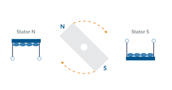
Figure 1: Spinning Bar Magnet Model for Step Motors
Figure 1 provides a simple magnetic model of step motor control. The rotor can be thought of as a spinning bar magnet that interacts with an externally controlled magnetic field (the stator). The rotational torque generated is zero when the N-S rotor field aligns with the stator N-S magnetic field (also called a B-Field), and maximum when the two fields are at an angle of 90 electrical degrees from each other. It’s worth noting that the actual internal construction of a step motor looks nothing this, but it's still a useful way to understand the nature of the motor's operation.
When the stator coils are driven with current a sinusoidal force 'valley' is created which drives the step motor to settle at a specific position. The more current that is driven through the coils, the greater the depth of the force valley. In this force profile of hills and valleys, wherever the curve is horizontal (flattest) there is no mechanical torque generated, and wherever the curve is steepest the generated torque is the largest.
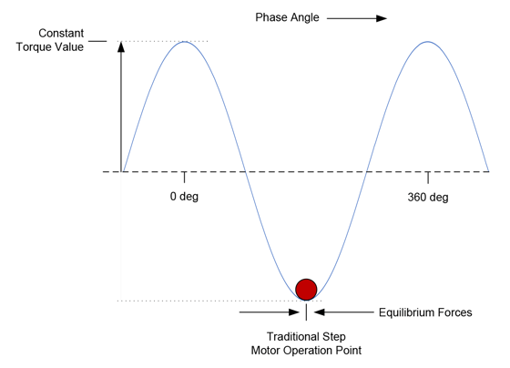
Figure 2: Traditional Step Motor Drive Scheme
As Figure 2 shows, in a traditional step motor drive scheme the motor settles to the 'bottom' of the force profile. At this point the net torque generated is zero because the motor is at an equilibrium point. This explains why position can be maintained in a step motor without an encoder or servo loop.
To create motion the motor controller moves this valley forward or backward by changing the stator B-Field phase via the external coil connections. The motor rotor than 'falls' forward or backward, maintaining itself at the bottom of the force valley in response. Think of a ball settling to the bottom of a trough.
You had me at full step
With this step motor magnetics primer behind us, we are ready to look at basic and advanced approaches to driving step motors.
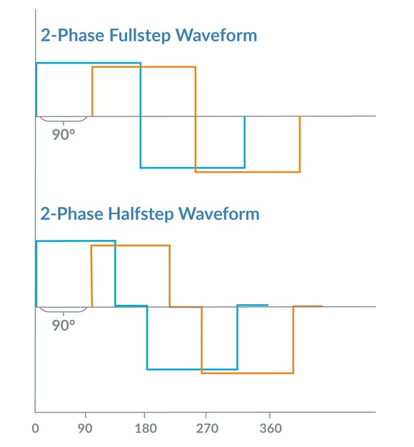
Figure 3: Traditional Step Motor Control Waveforms
Figure 3 shows two traditional waveforms for driving a step motor. Step motors are a multi-phase device, meaning multiple motor coils are electrically excited to create motion. Most step motors have two phases but more exotic configurations such as 3-phase or 5-phase also exist.
In the world of step motors, the phasing techniques that the amplifiers employ are given special names, in this case full step and half step drive. These different techniques refer to the number of power levels that are applied to each motor coil during an electrical cycle. Whichever drive method is used, the motor moves forward or backward when the external controller alters the electrical phasing.
Step motors are usually constructed with 1.8 mechanical degrees per full step (90 electrical degrees). So, this means a 1.8 degree step motor has 200 full steps per mechanical rotation. In addition to 1.8 degree step motors, other configurations exist such as .9 degree and 7.2 degrees.
It's not me, it's you
As convenient and simple as this scheme is, it has several drawbacks. Here is a rundown, with some important details that connect the magnetic model of the step motor to the problems we see with full and half step drive schemes.
- Noise & Vibration - Step motors are noisy during motion for a few reasons. If a full step or half step drive scheme is used the abrupt advancement of the commanded phase excites resonances (read that noise) in the rotor. Figure 4 provides a picture of this showing how the position of the rotor rings and takes time to settle when commanded to move to the next full step.
Another reason is the large number of electrical cycles per mechanical rotation. Just moving the rotor forwards or backwards requires the controller to constantly cycle the command voltages up and down for each phase, which induces noise in the coils and therefore the motor.
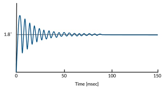
Figure 4: Ringing After Single Full Step Advance
- Mid-Range Instability - Another consequence of the step motor ringing after the phase angle is changed abruptly is a phenomenon called mid-range instability. Normally this ringing and settling process, which happens very rapidly, is not a big problem, but when the natural ringing frequency equals the commanded step rate a phenomenon called mid-range instability can occur which results in a dramatic reduction in available torque at that specific operating speed.
You got anything a little smoother?
The first controls upgrade we will introduce, one that is offered in quite a few step motor control ICs and digital drives is known as electronic resonance damping. The basic idea is that there are electronic techniques that can be applied to the step motor drive scheme which will reduce (damp) the tendency of the rotor to ring before settling to its equilibrium point.
Electronic damping has been available in one form another for well over twenty years and has been the subject of numerous patents. This is because while limited in its capability, most electronic damping techniques only require the addition of inductors, resistors, or capacitors and so don't add much cost to the step motor drive.
There are also more sophisticated electronic damping approaches that use microprocessor driven circuitry, or that require some amount of tuning by the user. While less prevalent in step motor control ICs, active damping circuitry is common in off-the-shelf step motor drives. When properly applied, they can dramatically reduce the problem of ringing and therefore reduce noise and mid-range instability.
In connection with electronic damping it's also important to mention the subject of current control, which we will cover in detail a bit later. Because of their high inductance, step motors are inefficient if the current flowing through their coils is not actively controlled. This technique, called current control, is common in motion control and applies to servo motors as well.
Motion control vendors don't always explain their current control technology separately from their anti-resonance technology, but the important point is that it is the net sum of how these two techniques perform that matter. Ultimately the proof is in the pudding, so you should look past fancy brand names and experiment with different controllers in your application to determine which one works best.
Somewhere over the rotor
Before we go overboard on upgrades to the control scheme, we shouldn't forget that all step motors are not created equal, and that the choice of step motor type affects noise and vibration as well.
Some motors, for example, have step sizes and configurations other than the industry standard 1.8 degree two-phase step motor. 0.9 degree step sizes are available, as are 3-phase and 5-phase motors. More phases mean smaller step sizes, potentially creating smoother motion. However, more phases also means the electronics will be more complicated and therefore more expensive.
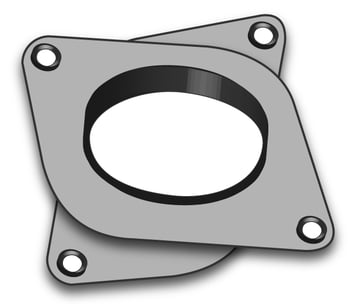
Figure 5: Step Motor Damper
Another purely mechanical approach to consider is dampers. These handy devices can reduce noise significantly and can reduce vibration to some extent as well. Figure 5 shows a typical step motor damper. Generally made of an elastomeric compound, they are installed between the motor and the load and do their job by introducing flexibility in the linkage of the two. The negative for these devices is that they add compliance, which can complicate your system's motion dynamics and reduce the end positioning accuracy.
While all the above mechanical options have their place, they have their drawbacks and it may be the case that their best days are behind them. Compared to twenty years ago, when sophisticated controls were quite expensive, today that is anything but true. Today, so much can be done with the controls to reduce noise, and at a very modest cost, that interest in higher phase step motors and mechanical dampers is probably waning.
Before moving on from this topic though, it is worth mentioning that properly sizing the motor for your application never goes out of style. So, plan on talking to your motor vendor so they can recommend the most suitable motor. Don't forget to tell them the max torque needed, the operating speed range, and the inertia of the load. Particularly in a direct drive setup, step motors operate more smoothly and more quietly when the motor is well matched (in particular, not overrated) to the load.
Step softly and carry a big stick
The next step up the control’s sophistication ladder is called microstepping. As Figure 6 shows, a microstepping waveform goes far beyond full step or half step and essentially drives the motor with sinusoidal waveforms. The number of microsteps per full step is often programmable, and in high end controllers microstep counts of 64 or even 256 microsteps per full steps are the norm.
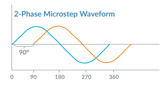
Figure 6: 2-Phase Microstep Waveform
Beyond just changing the waveform, microstepping has another major effect on the control system which is that the addressable resolution is increased. For example, in a full step scheme with a 1.8 degree step motor, there are 200 addressable locations per mechanical rotation. With a 64 microstep per full step microstepping controller and the same motor, there are now 200 * 64 = 12,800 addressable locations per mechanical rotation.
Is the addressable resolution equal to the actual accuracy? No. Going back to our magnetic step motor model diagram, the actual position of the settled rotor is the sum of the internal equilibrium-restoring force and whatever external forces may exist on the rotor. Therefore, in a given application, or for a given load, the exact actual profile path will vary a little bit from the theoretical commanded position.
The most dramatic effect of implementing a microstepping control scheme is the reduction in noise and vibration, and therefore also a reduction in mid-range instability. When first introduced, microstepping was a real breakthrough and helped breathe new life into the step motor marketplace. Today it is a common feature even in relatively low-cost step motor control ICs and off-the-shelf integrated drives.
Current we talk?
Beyond waveforms, there is a world of variation in how the current that flows through each coil (phase) of the step motor is managed. As it turns out these different current control techniques can have a large impact on noise & vibration, not to mention factors such as top speed and heat generation inside the motor.
Why do step motors even need a current controller? The answer is inductance and back-EMF. Inductance means that the voltage differential we introduce across the motor coil only reaches a steady state current after some time has elapsed. Back-EMF only makes matters worse, because it means that for a moving motor, the voltage differential may never generate the steady state current expected.
Current controllers handle both of these challenges by measuring the actual current flowing through the coil and applying voltage in such a way that the commanded current is achieved. For step motors active current control is particularly important because step motors have so many poles (electrical cycles per mechanical rotation), which means they need to rapidly and accurately go through the ups and downs of the current waveform to get the motor to move.
A complete treatise on current control techniques for step motors would take up a small book, but three techniques are worth talking about here, especially if we limit ourselves to switching amplifiers which, because of their efficiency, dominate the step motor amplifier space today.
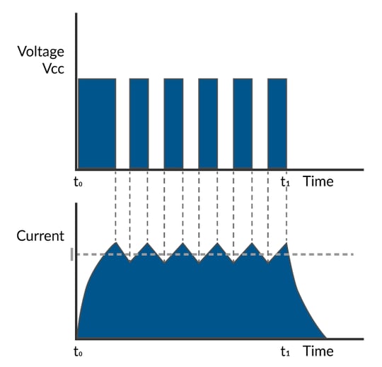
Figure 7: Fixed Off Time Current Control
The first current controller type we will discuss is called a fixed off-time current controller and is shown in Figure 7. It works by applying 100% of the motor voltage at the coil until a comparator indicates that the measured current exceeds the commanded (desired) current, at which point the voltage turns off for a fixed period of time. Some fixed off time controllers offer selectable slow decay versus fast decay control, which specifies whether current will be allowed to decay while circulating through the coil (slow decay) or while connected to ground (fast decay).
Fixed off time controllers are simple and have the benefit of needing minimal tuning to work for a wide range of step motor sizes and coil inductances. They have the disadvantage that current accuracy can be poor, particularly when the magnitude of the commanded current is decreasing. This is because during the fixed period of off time there is no ability to control the current, and so too little, or too much current may be dissipated via current decay. While selectable fast slow decay mode can help address this, this problem is somewhat inherent in this control scheme.
Divide, sample with an A/D, and conquer
While good-enough for some applications, more advanced controllers often use a different scheme called fixed frequency PWM (Pulse Width Modulation) current control. There are a few variations of this scheme, but a typical implementation is shown ion Figure 8.
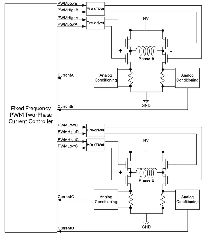
Figure 8: Fixed Frequency Current Measurement and Switch Control Diagram
The control scheme shown outputs switch commands for two bridges, each of which consist of four switches in an H-Bridge configuration. In addition to the PWM command itself other parameters of the MOSFET switch such as recharge time and shoot through protection timing are also controlled.
The current is measured using dropping resistors connected to the ground leg of each switch circuit. Leg current sensing requires a special algorithm to combine simultaneous measurements from multiple sensors. But it has the benefit that it allows explicit, highly accurate control of the motor coil's current at all times with no 'off' periods in the control cycle.
The net result of the improved current tracking from this control scheme is that the rotor will track more accurately, which in turn means there will be less noise and vibration.
Field of oriented control dreams
The final enhancement to our cavalcade of step motor current control schemes is shown in Figure 9 and is called Field Oriented Control, or FOC for short. While normally associated with Brushless DC motor control, FOC also has significant benefits when controlling step motors. These benefits include higher top speed and more efficient operation.
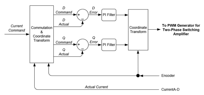
Figure 9: Field Oriented Control Data Flow Diagram
FOC is algorithmically complicated, and requires a separate treatment to explain fully, but by way of high level summary, FOC works by converting the rotating A and B step motor phase frame (assuming a two-phase step motor) to a non-rotating coordinate frame, referred to as the D phase current and the Q phase current. The commanded and actual D and Q phase currents are then subtracted and an error generated, which in turn is passed through a PI (proportional, integral) filter.
Finally, the output of the D and Q phase PI filters are converted back into the rotating reference frame and output as PWM voltage commands for each phase of the motor. The net result of FOC is modest improvements in noise and vibration, particularly at high speed, but significantly more torque generation at high speed which may allow a smaller step motor to be used for a given application.
You may also be interested in: Field Oriented Control (FOC) - A Deep Dive
I think you stepped on my servo
Interestingly, as techniques like microstepping and advanced current control solve one set of problems, another more subtle set are exposed. That is definitely the case here, because even if mathematically perfect sinusoidal current waveforms are used to drive the motor there can still be a fair amount of vibration.
This is due to the geometry of the stator/rotor teeth (a feature of all step motors) and peculiarities of the resultant B-fields. In short, step motors are complicated beasts and don't perfectly translate current waveforms into mechanical motion. The difference shows up as vibration, especially at higher speeds.
But a radical new drive technique called stepper servo (also referred to as closed loop stepper) has recently come on the scene that can address even this challenging and seemingly inherent problem. What makes this technique especially powerful is that it can use a generic non-custom step motor yet extract more performance out of it. This is accomplished by adding an encoder and operating the motor as, effectively, a commutated two-phase Brushless DC motor.
The fact that an encoder is needed means that truly low-cost applications will not be good candidates for stepper servo. But for applications that would otherwise gravitate toward Brushless DC motors, stepper servo is increasingly being considered as an option. In fact, in addition to offering a lower cost solution than a comparable Brushless DC motor, stepper servo can actually outperform Brushless DC motors in areas such as acceleration rate and torque output.
So how does stepper servo work? Stepper servo operation is different in three key ways from regular step motor operation. The first is that it requires an encoder to be attached to the step motor, one with a fairly high resolution. For standard 1.8 degree step motors you will want an encoder with no less than 2,000 counts per mechanical rotation, and for 7.2 degree step motors (which used to be a rare step motor configuration, but have become more popular due to stepper servo) 500 is a bare minimum.
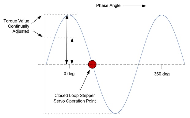
Figure 10: Stepper Servo Operation Point
The second difference is that stepper servo operation runs the motor like a Brushless DC motor and commutates the phase angle using the actual encoder position rather than the commanded position. Redrawing our force diagram, Figure 10 shows that commutated phasing means the step motor is operated at the steepest part of the force valley rather than at the equilibrium point.
This is very significant because rather than settling at its equilibrium (flattest) point of torque output, commutating the motor means we explicitly control it at its largest (steepest) point of torque output. This means that we can much more accurately and rapidly respond to the slight variations in rotor magnetics mentioned above that cause vibration even with perfect waveforms.
The third difference is that rather than being constant, the height and sign of the current waveform are continuously varied based on the output of a position PID loop, which is used to servo on the commanded position. Again, this is the same as how a Brushless DC motor is operated and along those lines a quick way to describe the stepper servo scheme as a two-phase Brushless DC motor.
Putting this all together, the control scheme used with the stepper servo looks quite different than the control scheme used with traditional open loop stepper motor controllers.
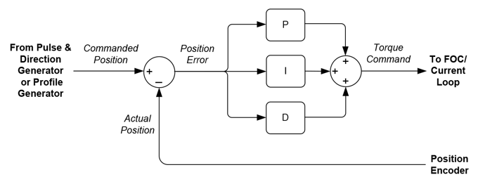
Figure 11: PID Control Loop
Figure 11 shows this scheme. There are three overall elements: a position PID loop, a current loop (often FOC), and a switch signal/current sense controller. As shown in the Figure above the PID loop inputs a commanded position, either from an external pulse & direction input or an internal profile generator, and uses the measured encoder position to generate a position error, and after filtering via the PID, a current command.
You may also be interested in: New Control Technique Combines Servo Performance with Step Motor Cost
Impress me
What are the advantages of operating a step motor this way? There are many, and they extend even beyond noise and vibration to address some of the other problems that step motors have:
- No Lost Steps - One immediate advantage is that losing steps is no longer a concern. Operated as a servo motor the encoder determines the location of the step motor and so the problem of losing steps no longer applies.
- Less Heat - A major advantage is that stepper servo runs the motor more efficiently, which means less heat generated in the motor. Commutated motors output just the amount of torque needed to achieve a desired motion profile, while traditionally controlled step motors are driven at a large constant current that must be sufficient to handle the worst-case motion.
- Accuracy - Accuracy here has two dimensions. Since the encoder explicitly measures the location of the motor the vagaries of determining the actual rotor settling position that come with a traditional step motor are eliminated.
The second is that the positioning accuracy becomes unlinked from the motor's degrees per step rating (for example 1.8 degs/step) and the resolution of the microstepping scheme. In a stepper servo the theoretical position resolution is determined solely by the resolution of the encoder, and therefore the same motor could achieve 2,000 resolvable locations (using an encoder with 2,000 counts per rotation) or 1,000,000 resolvable locations (using an encoder with 1,000,000 counts per rotation). - Velocity Smoothness - Another significant advantage is improved velocity smoothness. Because a traditional stepper motor controller doesn't explicitly measure and control the rotor position, the rotor angle tends to bounce around at the equilibrium point as it is influenced by external forces. The same motor operated in stepper servo mode can achieve much more accurate velocity tracking.
- Noise & Vibration - With the stepper servo technique the motor generates less noise than even a microstepping drive with high performance current control. While not necessarily as quiet as a typical Brushless DC motors, stepper servo pretty well kills the classic step motor noise problem.
Is Stepper servo the holy grail of step motor control? Not if you can't afford it. Compared to basic step motor control schemes described at the beginning of this article it will definitely increase cost. You will add the expense of an encoder, and the expense of the fancier stepper servo control scheme.
Encoders however are slowly but steadily getting cheaper and providing higher resolution, and despite the more advanced control technique employed with stepper servo, the cost of the electronics have come down a lot. Far from requiring a PLC, module, or bulky step motor drive, ICs that can handle all aspects of stepper servo control are now readily available for $20 or less.
Summary
Hopefully you have found this technical briefing on fixing, or at least improving, the issue of noise and vibration in step motors useful.
The choices presented generally follow the pattern of 'pay more to reduce noise more'. But in absolute terms control techniques that were once exotic and expensive are now common and cheap. For fans of step motors this is great news, and the marketplace backs up their enthusiasm. Far from slowly fading away to the power and performance of Brushless DC motors, step motors continue to gain design wins and if anything, are more popular than ever in motion applications that demand high performance and high reliability.
PMD Products That Provide Step Motor Control
PMD has been producing ICs that provide advanced position and torque control of step motor, DC Brush, and Brushless DC motors for more than twenty-five years. Since that time, we have also embedded these ICs into plug and play modules and boards. While different in packaging, all of these products are controlled by C-Motion, PMD's easy to use motion control language and are ideal for use in pick & place machines, laboratory equipment, liquid handling, and a wide variety of other high performance motion control applications.
Juno Stepper Motor Control ICs
The MC74113 and MC74113N are members of the Juno family of ICs and are perfect for building your own low cost, high performance microstepping or stepper servo motor controller. Juno ICs feature FOC (Field Oriented Control), two-phase waveform generation, high/low switching amplifier control signals, leg current sensing, and more. Available in packages as small as 7mm x 7mm and costing $12 in quantity, these ICs are an ideal solution to upgrade your existing pulse & direction controller, or for starting your next machine design project from scratch.
Learn more >>
MC58113 Series ICs
The MC58113 series of ICs are core members of PMD's popular Magellan Motion Control IC Family and provide advanced position control for BLDC, DC Brush, and step motors alike. Standard features include S-curve profiling, FOC (Field Oriented Control), high/low switch signal control, direct encoder & pulse & direction input, and much more. Whether used for laboratory automation, pump control, pointing systems, or general-purpose automation, the MC58113 family of chips are the ideal solution for your next machine design.
Learn more >>
ION Digital Drives - Stepper Motor Drivers
ION® Digital Drives combine a single axis Magellan IC and an ultra-efficient digital amplifier into a compact rugged package for control of step motors, DC Brush, and Brushless DC motors. In addition to advanced S-curve & trapezoidal point to point moves, cam profile support, and advanced motor performance analysis software, IONs are loaded with safety functions such as over current, over voltage, and over temperature detect. IONs are easy to use plug and play devices that will get your next pump controller, laboratory equipment, patient treatment, or automation design project up and running in a snap.
Learn more >>
More in this series:
You may also be interested in:
- How to Control Stepper Motors
- Motion Controller Design Architectures - A Deep Dive
- S-Curve Motion Profiles - Vital For Optimizing Machine Performance
- Closed Loop Steppers Drive New Motion Control Applications
- Field Oriented Control (FOC) - A Deep Dive