More and more motion control systems are dedicated to the precise movement of liquids. While pumps and compressors have been around for a long time, the recent driver of this technology is laboratory automation - particularly machines used in healthcare, life sciences, pharmacology, chemicals, scientific instrumentation, agriculture, and packaging.
There are two overall motion control tasks related to fluid handling. First is the actual movement/control of the fluid itself. This means precisely delivering a particular volume of fluid, a particular flow rate, or a particular pressure. Second is the movement of the containers which hold these fluids, such as test tubes, microscope slides, and a variety of other carriers.
Although we don't normally think of moving fluid as a motion control problem, as we shall see it most certainly is. So sit back, relax, and pour yourself a tall glass of your favorite liquid beverage as we take a deep dive into precision fluid handling.
I bet you say that to all the liquid handling robots
As it turns out liquid handling automation has been around for years, and at the core, these machines share some common characteristics. In particular, they require the ability to move to various points on a work surface, draw in (aspirate) fluid from a container, and deliver (dispense) this liquid to some other container.
Figure 1 shows the liquid handling portion of such a system schematically. The major elements are the pump, the connective tubing, the working fluid, and the aspirate/dispense head (often called the tip).
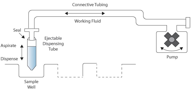
Figure 1: Fluid handling system schematics
Along the way we need to control the amount of liquid being drawn in or dispensed very accurately, and isolate this liquid sample from previously handled samples to avoid contamination.
How is this done? While the pump does the heavy lifting here, a clever arrangement of what is called the working fluid (often air) ensures that the liquid samples don't get contaminated. When air is drawn into the pump, the suction draws in the fluid from the well. The amount of fluid drawn is always less than the volume of the dispensing tip, ensuring that no sample fluid enters the pump connective tubing. When the pump expels air, the positive pressure pushes the sample fluid out of the tip.
Many liquid handling systems support multiple tips so that liquid can be drawn in and dispensed to more than one port at a time. Some models provide more than 1,000 such ports!
We want to… pump you up
Pumping liquid in accurate measures is at the core of our fluid handling system, so let's take a look at a few different pumps that might be used. It's worth noting that all of these mechanical pump types can be used in non-precision applications as well. The difference between a precision application and general pump applications is often just the type of motion controls that are used.
Figure 2 shows one of the most common types of pumps for high precision liquid handling. Known as a piston or syringe pump, as the name suggests, the liquid is dispensed or aspirated by moving a sealed plunger through a tube.
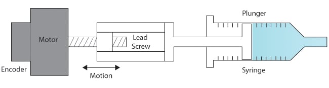
Figure 2: Syringe pump
Piston pumps are capable of very high precision. Most use a lead screw driven by a step motor or servo motor. The higher the motor's positioning resolution, the finer the dispensing resolution. Because of this piston pumps have wide application, not only for liquid handling robotics such as described above, but for a host of other applications such as liquid chromatography, drug infusion, chemical mixing, and much more.
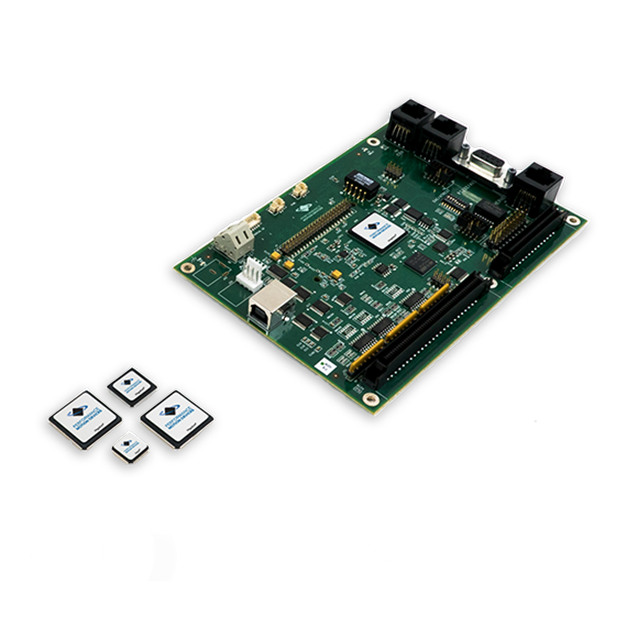
Have you met Magellan? Magellan is a high-performance motion control and positioning IC.
A single-piston pump has a fixed total displacement. While liquid can be ejected or drawn in, the total volume of liquid transfer is limited to the volume of the syringe. For continuous flow, piston pumps can still be used, but two or more pistons must be arranged so that as some pistons are dispensing, others are drawing in fluid. Devices known as check valves, properly arranged in line with the pistons, limit flow to one direction to provide continuous flow.
Can you draw me a diaphragm?
A variation of the syringe pump (perhaps more of a distant cousin) is the diaphragm pump, shown in Figure 3. The similarity to the syringe pump is that a seal moves in and out, thereby displacing the liquid. The difference is that the seal is driven in a reciprocating manner, similar to a gasoline engine, alternately drawing fluid in, and dispensing fluid out. Check valves are used to maintain fluid flow in one net direction.
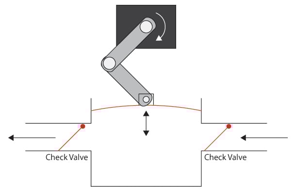
Figure 3: Diaphragm pump
Because a simple spinning motor can generate the reciprocating motion needed for this type of device, diaphragm pumps are very popular and truly ubiquitous. They have even been used in artificial hearts, although in this case external air pressure rather than spinning motors cause the diaphragm to move in and out and thereby pump blood.
Coupled with positioning motion controls diaphragm pumps can deliver reasonable accuracies of measured liquid. However, for our general purpose liquid handling system described above, a major disadvantage is that liquid flows in only one direction. So for bi-directional pumping two diagram pumps, one to draw liquid in, and one to dispense liquid, are used.
You had me at peristaltic
Figure 4 shows a completely different kind of pump, which, like the syringe pump and the diaphragm pump, has a wide range of applicability in medical, chemical, and general scientific liquid handling applications. Known as the peristaltic pump, this type of pump uses a roller to squeeze a liquid-containing flexible tube, thereby displacing the liquid in the direction of the roller movement.
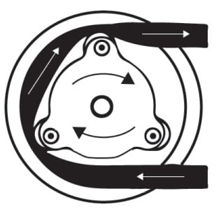
Figure 4: Peristaltic pump
The big advantage of this type of pump is the separation of the pumping mechanism (the roller) from the medium (the tubing) that holds the liquid. This is ideal for motion control applications where liquid contained in sterile tubing, catheters, or other packaging must be pumped without contacting the contents of the packaging. Dialysis machines, blood transfusion machines, and many similar applications use these pumps for this reason.
For precision liquid handling the main disadvantage of peristaltic pumps is a lack of accuracy. Flexible tubes are elastic, which means their volume over a particular distance may vary. In addition, the liquid is delivered in 'packets' consisting of the space between two roller engagement points. So the fluid flow tends to be pulsed. There are arrangements of rollers that minimize this effect, and control loops that can handle such variable loading dynamics are a must, but compared to syringe pumps fluid output is not as constant.
We're operating in a vacuum
Finally, for precision fluid handling, it is possible to use general purpose air pumps coupled with sensors to deliver surprisingly precise measures of fluid. This type of arrangement is shown in figure 5.
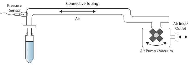
Figure 5: Air pump
Here's how it works. A general purpose air pump that can create positive or negative pressure is connected to the working fluid tube. Sensors measure the actual air pressure imparted by the pump. To determine the amount of liquid transferred, the air pressure is monitored at regular intervals and a previously-created lookup table that converts pressure differential to flow rate is used to sum the total amount of liquid transferred.
The advantage of this arrangement is compactness and low cost. Air pumps are inexpensive and come in a wide range of shapes and sizes. At the same time, electronic pressure sensors are continuously becoming smaller and less expensive. So for many applications, this basic pumping system is perfectly adequate.
May I have ten thousand samples please?
Now that we have looked at how we can pump fluids, let's focus on what we are pumping them into and how we are moving them from point A to point B.
There are two strategies for building a general purpose liquid handling platform such as described at the beginning of this deep dive. You can move the robot to the fluid, or you can move the fluid to the robot. Most systems choose the former. The portion of the liquid handling system that draws in and dispenses fluid dispensing moves, and the containers that store the liquids stay stationary.
Are there special motion control techniques that apply to the problem of moving objects that hold liquids? The answer is yes… and no. A big 'yes' stems from the high level of reliability that is needed for such valuable payloads. This is similar to industries such as semiconductor equipment, where processed wafers can have a value of $100,000 or more. So the motion must be very robust and reliable.
Along those lines, in liquid handling automation position encoders are the norm, even when step motors are used, which would otherwise not require an encoder for positioning. Why is this? As the saying goes, 'stuff happens'. There could be a glass shard that found its way to a mechanism or a long-ago spilled liquid that is slowly degrading a linear slide. Having an encoder on the motor allows such mechanical problems to be detected before the load is lost.
Say hello to 1,536 of my little friends
Machine designs that can move slides, test tubes, or special carriers called microplates (which can hold as many as 1,536 separate liquid samples each!) tend to be mechanically complex and on the large side, in the range of breadboxes to full-sized refrigerators.
Whatever their size, the wider the motion range and the heavier the load, the greater the importance of minimizing vibration. Vibration is the enemy of reliability and accuracy. Figure 6 shows a stylized mechanism with an actuator (in this case a rotary motor), an end effector, and a mechanism base.
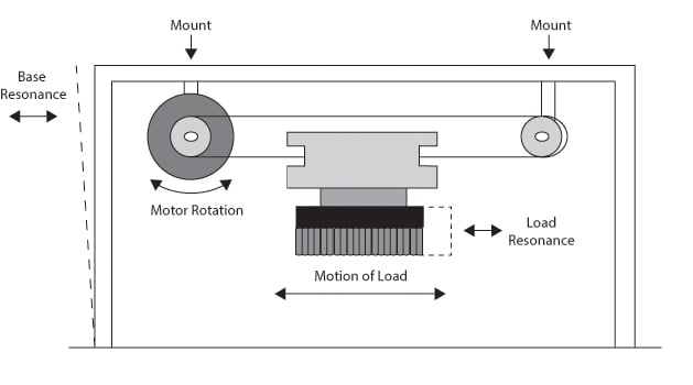
Figure 6: Stylized Mechanism with an actuator, end effector, and mechanism base
As Newton taught us, every action has an equal and opposite reaction, so if the motor drives the end effector with a given force, an equal and opposite force will be injected into the mechanics that support the end effector.
Both the end effector and the support mechanics tend to have their own resonance points. So to get a handle on all of this, it's always a good idea to perform a resonance scan of the mechanics. See a deep dive on Mechanical Resonant Frequency for more details, but the basic idea is to operate the motor in a sinusoidal back and forth motion, sweeping from a low frequency to a high frequency, and observing the response in the mechanics.
Such a scan is known as a Bode plot. Even if we don't explicitly measure the mechanics, the servo motor response will tend to show resonance points in the mechanics because resonances will reflect energy back into the motor.
I think therefore I S-curve
Once we are ready to optimize controls, the first step is to select motion profiles that minimally excite resonances in the mechanics. How do we do this? What kinds of motion inject the least amount of vibration energy into the mechanics?
In short, the answer to both questions is that we minimize jerk. Change in the rate of acceleration, or jerk, is a primary source of vibrational energy injected into the mechanics. So less is more. As figure 7 shows, in a trapezoidal move there are three segments; accel, coast, and decel. The change in acceleration at the segment changes is, at least in theory, infinite because the duration of the acceleration transition is zero.
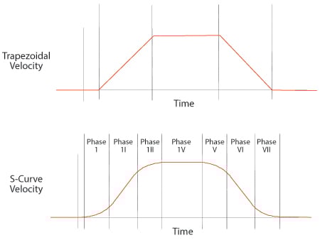
Figure 7: Trapezoidal vs. s-curve profiles
By adding an S-segment, which is an interval over which the acceleration transitions from one value to another, the total vibrational energy as well as the frequency range of injected vibration is reduced.
In a perfect world, you would drive the profile so as to avoid specific resonance frequencies. In practice, trial and error will help you determine what works best. The trick is to add a small amount of "S" so that the total move duration is not unduly lengthened, while still dramatically reducing the mechanical vibration.
To illustrate this, we have prepared a video showing the movement of a truly 'compliant' load, one befitting this deep dive's subject matter… liquid!
In the two profiles shown, the top velocity and the acceleration are exactly the same. The difference is a small amount of "S" - a transition between acceleration changes. As you can see though, the difference in how much the load vibrates is dramatic.
The particular setup shown drives a linear brushless motor using an Atlas® digital amplifier. The trapezoidal and s-curve profiles are generated by Magellan® positioning IC, which also closes the servo position loop. It is worth noting that the very same concepts apply even when using step motors. This is because the profile generator comes before the servo loop. So profile optimizing should be performed whether or not a servo loop is used to control the motor position.
FeedForward me!
With our profiles optimized to minimally inject vibration, we are ready to add one more control element that is important for servo-based machines. This control element is feedforward.
Assuming a Cartesian XYZ type motion system, applying feedforward is pretty simple. By the way, if you want to explore non-Cartesian mechanics (which is definitely a bit more of a challenge), check out the deep dive on Motion Kinematics.
In any case, we want to inject an acceleration-proportional signal directly into the position loop that offsets the inertial forces our load and end effector will experience. What forces are these? Once again our friend Newton tells us that objects at rest tend to stay at rest, and objects in motion tend to stay in motion. So this means during acceleration the load will lag, and during deceleration, the load will lead.
While it may be possible to calculate the feedforward gain amount, the simplest procedure is to once again use trial and error. Here's how you do it: Set up a simple PID loop with no integrator, just moderate P and D. Now set up your exerciser software to capture the servo error over the entire move. Start with small accel feedforward values and increase until you notice the servo error is minimized. Don't forget to check out the move forwards and backwards. Some sample capture traces are shown in figure 8.
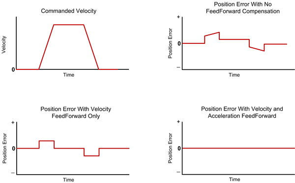
Figure 8: FeedFoward
Feedforward terms are 'open loop', so they can not actively adjust for changes in the system such as increased mechanical wear and tear due to aging, or different loads. This means you should pick average values for feedforward gains, but don't expect perfection in real-world conditions.
What about velocity feedforward? Most motion controllers offer this feature, so if there are velocity-proportional forces in your system, by all means, apply velocity feedforward to compensate.
Finally, if you have a Z-axis under servo control, consider using your motion controller's PID bias setting (sometimes called a motor bias or motor command offset) to feedforward a constant value that counteracts the force of gravity.
Summary
Moving liquid, and moving containers that hold liquid, represent two critically important tasks in the fast-paced field of laboratory automation. Such machines make our modern medical, chemical, and pharmaceutical worlds possible, and are an increasingly important user of motion control technology.
The keys to machine design success are understanding what type of fluid pump will work best in your motion control application and selecting motion controls that give you the fluid pumping accuracy you need.
When you are building your robotic mechanism, focus on reliability and performance by optimizing the mechanics using resonance analysis, minimizing injected vibration by tuning the profiles, and selectively useful feedforward to make the job of the PID loop as easy as possible.
I hope you enjoyed this primer on motion control as applied to automated liquid handling systems.
Written by Chuck Lewin
Founder and CEO
Performance Motion Devices, Inc.
You may also be interested in:
- Improving Liquid Handling Robot Throughput
- Mathematics of Motion Control Profiles
- New Measurement Techniques Drive New Formats
Stay ahead of the competition.
If your existing equipment needs a performance boost or if you need to develop a new product in the shortest development time possible, learn about motion control solutions from Performance Motion Devices.
- 2X faster development
- Motion solutions from ICs to turn-key boards
- Easy to implement
- Always supported