The Magellan MC58000 and MC55000 Motion Control ICs provide advanced motion control for medical, scientific, automation, industrial, and robotic applications. Available in 1, 2, 3, and 4-axis versions, these flexible, programmable devices control Brushless DC, DC Brush, and step motors.
Magellan Motion ICs are complete motion controllers requiring only an external amplifier to be functional. They are driven by a host using either a parallel bus, SPI (Serial Peripheral Interface), CANbus 2.0B, or RS232/485 serial. User selectable profiling modes include S-curve, trapezoidal, velocity contouring and electronic gearing. PID servo loop compensation utilizes a 32-bit position error and includes velocity and acceleration feedforward. High performance FOC (field oriented control) provides high accuracy, ultra-low noise motor operation.
All Magellan Motion Control ICs provide a flexible and powerful instruction set to initialize and control motion axes, monitor performance, and synchronize overall machine behavior. Working with Magellan ICs and Pro-Motion® development software makes it fast and easy to graph and analyze system performance; while C-Motion® language allows you to develop your own application using C/C++ or .NET languages.
Available Configurations
There are two groups of Magellan Multi-Axis Motion Control ICs, MC58000 series ICs and MC55000 series ICs.
Note: MC5x113 ICs, which are single axis Magellan motion control ICs that also integrate current control are detailed in a separate data sheet here.
MC58000 Series: Positioning Motion Control ICs providing 1 to 4 axes of control for Brushless DC, DC Brush and step motors in a two-IC package.
MC55000 Series: Pulse and direction output positioning ICs providing 1 to 4 axes of control for step motors in a two-IC package.
Two LQFP ICs comprise the Magellan MC5x000 Motion Control chipset; a 144-pin Command Processor (CP) chip and a 100-pin Input/Output (IO) chip. These ICs are ordered separately.
Ordering Information
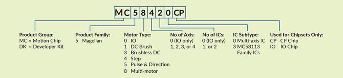
CP (Command Processor) IC Part Numbers
|
Part Number (P/N)
|
Number of Axes
|
Motors Supported
|
|
MC58120CP
|
1
|
DC Brush, Brushless DC, step motor
|
|
MC58220CP
|
2
|
DC Brush, Brushless DC, step motor
|
|
MC58320CP
|
3
|
DC Brush, Brushless DC, step motor
|
|
MC58420CP
|
4
|
DC Brush, Brushless DC, step motor
|
|
MC55120CP
|
1
|
Step motor (pulse & direction format)
|
|
MC55220CP
|
2
|
Step motor (pulse & direction format)
|
|
MC55320CP
|
3
|
Step motor (pulse & direction format)
|
|
MC55420CP
|
4
|
Step motor (pulse & direction format)
|
IO (I/O) IC Part Numbers
|
Part Number (P/N)
|
Number of Axes
|
Motors Supported
|
|
MC50000IOSE8G
|
1-4
|
Provides IO chip functions for all of the above CP ICs.
|
Developer Kits
Developer Kits are available for both MC58000 Series ICs and MC55000 series ICs as shown in the table below:
|
DK Part Number (P/N)
|
Installed Motion IC
|
Motors Supported
|
|
DK58420
|
MC58420
|
DC Brush, Brushless DC, step motor
|
|
DK55420
|
MC55420
|
Step motor (pulse & direction format)
|
Magellan Multi-Axis Motion Control ICs Feature List
- Positioning Motion Control ICs for Brushless DC, DC Brush and step motors in a 1 to 4-axis package
- S-curve, trapezoidal, velocity contouring, and electronic gearing profiles
- Serial RS232/485, Parallel, CANbus, and SPI (Serial Peripheral Interface) communications
- Advanced PID filter with velocity and acceleration feedforward
- High performance current control & PWM signal generation
- Velocity, position, and acceleration changes on-the-fly
- Field oriented control
- High speed (up to 5 Mpulses/sec) pulse & direction output
- Incremental encoder quadrature input (up to 25 Mcounts/sec)
- Programmable loop time to 50 μsec
- Dedicated motion trace function for performance optimization
- Overcurrent, overvoltage, and overtemperature monitoring
- Two directional limit switches, index input, and home indicator per axis
- Axis settled indicator, tracking window and automatic motion error detection
- Programmable dual biquad filters
- Programmable acceleration and deceleration values
- Two directional limit switches, high speed index, and home inputs per axis
- Dual loop encoder input
- 3.3 V operation, packaged in 144- or 100-pin TQFP
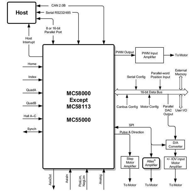
Connection Diagram
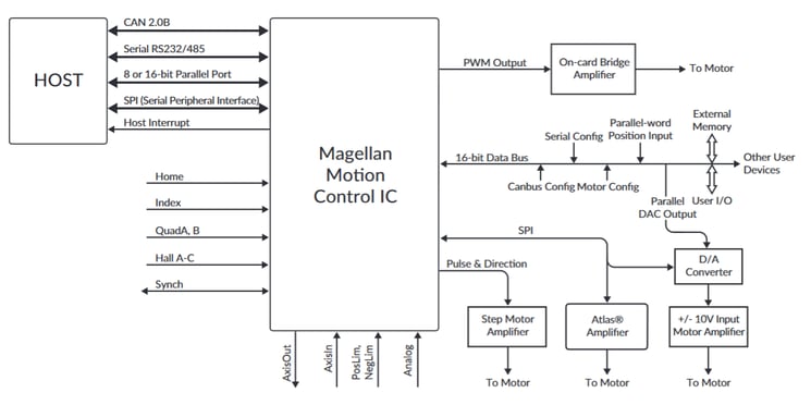
Figure 1: MagellanMC5x000 ICs Connection Diagram
Specifications
Amplifier Connection Options
Magellan MC5x000 ICs are designed to be compatible with onboard amplifier modules such as PMD’s Atlas Digital Amplifiers, Juno Torque Control ICs, general purpose onboard amplifier circuitry, and off-board cable connected amplifiers.
|
Atlas Digital Amplifier
|
|
|
|
Amplifier SPI bus interface
|
16-bit continuous torque command
|
|
|
Voltage range
|
12-56V, single voltage supply
|
|
|
Power range
|
Low (75W), Medium (250W), High (500W)
|
|
|
Safety
|
Overcurrent, over/undervoltage, overtemperature, I2T
|
|
|
Package
|
Ultra-compact (27 x 27 x 13 mm), compact (39 x 39 x 15 mm)
|
|

|
Juno Torque Control IC
|
|
|
|
Amplifier SPI bus interface
|
16-bit continuous torque command
|
|
|
Microstep synthesis rate
|
40 kHz
|
|
|
Current loop rate
|
20 kHz
|
|
|
Bridge types supported
|
Triple half-bridge (Brushless DC motor), H-bridge (DC Brush motor)
|
|
|
Control features
|
FOC, shoot through protection, up to 120 kHz PWM rate, i2T current foldback
|
|
|
Juno Step Motor Control IC
|
|
|
|
Amplifier SPI bus interface
|
Pulse & direction
|
|
|
Current loop rate
|
20 kHz
|
|
|
Microstep resolution
|
Up to 256 microsteps/full step
|
|
|
Bridge types supported
|
Dual H-bridge (two-phase step motor)
|
|
|
Control features
|
FOC, shoothrough protection, up to 120 kHz PWM rate
|
|

|
On-board PWM amplifier circuitry
|
|
|
PWM output rate
|
20, 40, or 80 kHz
|
|
Current loop rate
|
20 kHz
|
|
PWM output modes
|
High/Low, Sign/Magnitude, 50/50
|
|
Analog output modes
|
16-bit SPI motor command word
|
|
External +/- 10V input amplifier
|
|
|
Amplifier SPI bus serial DAC
|
16 bits
|
|
Pulse & direction input amplifier
|
|
|
Pulse and direction output rate
|
Up to 4.9 Mpulses/sec
|
Functional Overview
Each axis within the MC5x000 ICs (from 1 to 4 depending on part number) inputs the actual location of the axis using either incremental encoder signals or a parallel-word input device such as an absolute encoder, analog to-digital converter, resolver, or laser interferometer. Regardless of the encoder input method, this position information is then used to maintain a 32-bit actual axis position counter.
A trajectory generator then calculates a new desired position at each cycle time interval, which is based on the profile modes and parameters programmed by the host, as well as on the current state of the system. The cycle time is the rate at which major system parameters are updated.
For motion control ICs with servo motor support (MC58000), the output of the trajectory generator is combined with the actual encoder position to calculate a 32-bit position error, which is passed through a PID position loop.
The resultant value is then output by the motion control IC to an external amplifier using either PWM, DAC, or SPI Atlas-compatible signals. If the axis is configured for a brushless DC motor, then the output signals are commutated, meaning they are combined with information about the motor phase angle to distribute the desired motor torque to two- or three-phased output commands. For axes configured for step motors the output of the trajectory generator is converted to either microstepping signals (MC58x20), or pulse and direction signals (MC55x20) and is then output accordingly.
If Atlas Digital Amplifiers are used then the hardware connection format is always a four-signal SPI bus. Magellan Motion Control ICs automatically provide the protocol message formats needed by Atlas to support the motor type being used, either DC Brush, Brushless DC, or step motor.
Host communication to and from Magellan Motion Control ICs is accomplished using a parallel-bus interface (8 or 16-bit bus available), an asynchronous serial port, or a CAN 2.0B interface. For serial communications the transfer protocol may be either point-to-point or multi-drop.
Regardless of the hardware interface method, communication to and from Magellan Motion Control ICs occurs using short commands sent or received as a sequence of bytes and words. These packets contain an instruction code word that tells the motion control IC which operation is being requested. It may also contain data sent to, or received from, the motion control IC.
These commands are sent by a host microprocessor or host computer executing a supervisor program that provides overall system control. The Magellan Motion Control IC is designed to function as the motion engine, managing highspeed dedicated motion functions such as trajectory generation, safety monitoring, etc., while the host software program provides the overall motion sequences.
Typical Applications
Multi-axis Motion Control Board for DC Brush, Brushless DC, or Step Motors Using On-Card Atlas® Digital Amplifier Modules
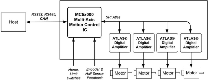
Figure 2: Magellan using Atlas Amplifiers with No Microcontroller
In this application the Magellan MC5x000 Motion Control IC forms the heart of a dedicated multi-axis motion controller card. The Magellan IC-based controller is commanded directly by a host via an RS232, RS485, or CAN bus network connections and provides high performance profile generation and position control of DC Brush, Brushless DC, and step motors. Quadrature encoders provide motor position feedback, and if Brushless DC motors are used Hall sensors provide commutation feedback. With step motors encoder feedback is optional.
Atlas Digital Amplifiers are single axis devices which receive a continuous stream of torque or pulse & direction commands from the Magellan IC. Atlas amplifiers come in three power levels, 75W, 250W, and 500W and support DC Brush, Brushless DC, and step motors. Additional supported signals include a home switch, directional limit switches, general purpose AxisIn and AxisOut signals, and more.
To power the card an external power supply provides the motor voltage (HV) which powers a DC-to-DC converter used to generate 3.3V DC for card logic. The Atlas amplifiers also input this same HV voltage to power their internal logic as well as a 5V output which can be used to power motor encoders and hall sensors.
In this diagram four axes are shown but 1, 2, 3, as well as 4-axis versions of the Magellan IC are available.
Multi-axis Motion Control Board for DC Brush, Brushless DC, or Step Motors Using On-Card Microcontroller For Machine Program Execution
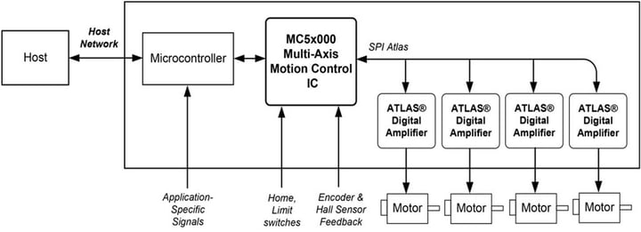
Figure 3: Magellan using Atlas Amplifiers with Microcontroller
In this application the Magellan MC5x000 Motion Control IC provides motion control functions such as profile generation and servo loop but is commanded locally, by an on-card microcontroller. This microcontroller may operate the machine standalone, or may process commands from a host interface and pass various motion commands to the Magellan Motion Control IC. Quadrature encoders provide motor position feedback, and if Brushless DC motors are used Hall sensors provide commutation feedback. With step motors encoder feedback is optional.
Atlas Digital Amplifiers are single axis devices which receive a continuous stream of torque or pulse & direction commands from the Magellan IC. Atlas amplifiers come in three power levels, 75W, 250W, and 500W and support DC Brush, Brushless DC, and step motors. Additional supported signals include a home switch, directional limit switches, general purpose AxisIn and AxisOut signals, and more.
To power the card an external power supply provides the motor voltage (HV) which powers a DC-to-DC converter used to generate 3.3V DC for card logic. The Atlas amplifiers also input this same HV voltage to power their internal logic as well as a 5V output which can be used to power motor encoders and hall sensors.
In this diagram four axes are shown but 1, 2, 3, as well as 4-axis versions of the Magellan IC are available.
Multi-axis Motion Control Board for DC Brush, Brushless DC, or Step Motors Motors Using On-Card Juno® Amplifier Control ICs
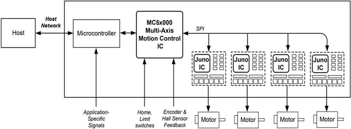
Figure 4: Magellan using Juno IC Amplifiers with Microcontroller
In this application the Magellan MC5x000 Motion Control IC provides high performance profile generation and position control of DC Brush, Brushless DC, and step motors. Quadrature encoders provide motor position feedback, and if Brushless DC motors are used Hall sensors provide commutation feedback. With step motors encoder feedback is optional.
This board is similar to the previous application except that in this design rather than Atlas Digital Amplifiers, Juno Amplifier Control ICs are used. These ICs receive a continuous stream of torque or pulse & direction commands from the Magellan IC and generate PWM bridge input and output control signals to drive on-card digital switching amplifier circuitry. In addition, Juno ICs input analog feedback signals use to provide precise current control and amplifier safety monitoring. Additional supported signals include a home switch, directional limit switches, general purpose AxisIn and AxisOut signals, and more.
To power the card an external power supply provides the motor voltage (HV) which powers a DC-to-DC converter used to generate 3.3V DC for card logic, 5V for encoder and hall sensor power, and 15V for amplifier pre-driver circuitry.
Multi-axis Motion Control Board for DC Brush, Brushless DC, or Step Motors Using Single-IC On-Card Amplifiers
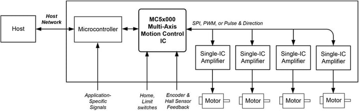
Figure 5: Magellan using Single-axis IC Amplifiers with Microcontroller
In this application the Magellan MC5x000 Motion Control IC provides high performance profile generation and position control of DC Brush, Brushless DC, and step motors. Quadrature encoders provide motor position feedback, and if Brushless DC motors are used Hall sensors provide commutation feedback. With step motors encoder feedback is optional.
This board is similar to the previous application except that in this design single-IC amplifiers are used. Available for step motors, DC Brush, and Brushless DC motors these ICs typically can provide up to 4 amps of current. Relative to an Atlas Digital Amplifier or Juno IC based amplifier the performance is not as high, but may still be adequate for many applications. Additional supported signals include a home switch, directional limit switches, general purpose AxisIn and AxisOut signals, and more.
To power the card an external power supply provides the motor voltage (HV) which powers a DC-to-DC converter used to generate 3.3V DC for card logic, and 5V for encoders (if used). Most single-IC amplifiers accept a single HV power input.
Multi-axis Motion Control Board for DC Brush, Brushless DC, or Step Motors Using Off-Card Amplifiers
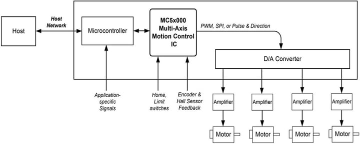
Figure 6: Magellan using Off-board Amplifiers with Microcontroller
In this application the Magellan MC5x000 Motion Control IC provides high performance profile generation and position control of DC Brush, Brushless DC, and step motors. Quadrature encoders provide motor position feedback, and if Brushless DC motors are used Hall sensors provide commutation feedback. With step motors encoder feedback is optional.
This board is similar to the previous applications except that in this design there are no on-card amplifiers and instead +/- 10V analog output signals are used to command off-card amplifiers. These +/- 10V amplifier command signals are generated from 16-bit data words output by the Magellan IC using on-card D/As. To control step motors pulse & direction signals are used rather than +/-10V signals, and these digital signals connect to off-card step motor amplifiers.
To power the card an external power supply provides the motor voltage (HV) which powers a DC-to-DC converter used to generate 3.3V DC for card logic, 5V for encoders (if used), and +/- 12V for generation of the +/- 10V output signals. Alternatively one or more of these voltage supplies may be provided via individual power inputs.
MC5x000 Key Product Features
Advanced Instruction Set
Here is a list of some of the functions provided by Magellan MC5x000 Motion Control ICs:
- Profile generation
- Quadrature encoder processing and index capture
- DC Brush and Brushless DC servo loop closure
- Breakpoint processing
- Trace
- Motion error detection, tracking windows, and axis-settled indicator
- Limit switch processing
- Current control
Example Magellan Instructions
The Magellan instruction set is flexible and powerful. The following very simple example, which sets up and executes a trapezoidal profile, illustrates just a small part of the overall command set. In addition, this small sequence shows the look and feel of C-Motion, PMD’s C-language callable motion interface that handles communications to and from all machine controller board resources.
|
PMDSetProfileMode(&hAxis1, PMDProfileTrapezoidal);
|
// set profile mode to trapezoidal for axis 1
|
|
PMDSetPosition(&hAxis1, 12345);
|
// load a destination position for axis 1
|
|
PMDSetVelocity(&hAxis1, 223344)
|
// load a velocity for axis 1
|
|
PMDSetAcceleration(&hAxis1, 1000)
|
// load an acceleration for axis 1
|
|
PMDSetDeceleration(&hAxis1, 2000)
|
// load a deceleration for axis 1
|
|
PMDUpdate(&hAxis1);
|
// initiate the move
|
hAxis1 is a handle to a structure known as a PMDAxisHandle. There are several different C-Motion structures, and in general, they are used to make accessing the Magellan axes simpler and more flexible. In particular, by developing code with C-Motion, it is very easy to change the physical location of a PMD axis without any changes to the developed C-Motion code sequences. This is called axis virtualization and is a powerful feature of the C-Motion/Magellan IC system.
Seven-Segment S-Curve Profiling
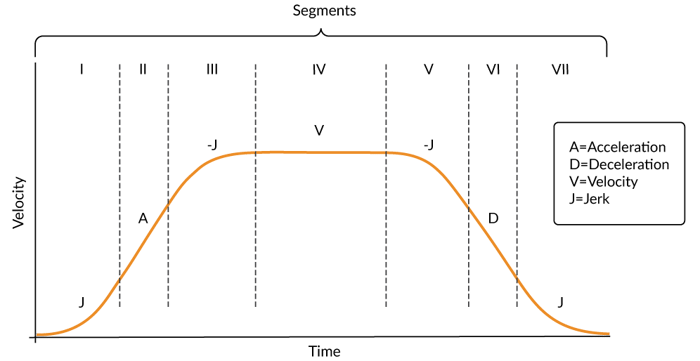
Figure 7: S-curve Profile
While trapezoidal profiles are very common in motion control, the S-curve profile is actually the workhorse for point to point motion because of its greater ability to control the amount of vibrational energy injected into the load. S-curve profiles add a limit to the rate of change of acceleration to the trapezoidal profile. This parameter, known as jerk, specifies the maximum change in acceleration per unit time.
Figure 7 shows a typical S-curve profile. In Segment I, the S-curve profile drives the axis at the specified jerk (J) until the maximum acceleration (A) is reached. The axis continues to accelerate linearly (jerk = 0) through Segment II. The profile then applies the negative value of the jerk to reduce acceleration to 0 during Segment III. The axis is now at maximum velocity (V), at which it continues through Segment IV. The profile will then decelerate in a manner similar to the acceleration stage, using the jerk value first to reach the maximum deceleration (D) and then to bring the axis to a halt at the destination.
Position PID Loop With Feedforward
This tired old PID algorithm is getting a new look and feel, but lets face it hasn’t changed, content-wise, since the late 1990s. Thankfully everything old is new again! Here we go…
The servo filter used with the Magellan Motion Control ICs is a proportional-integral-derivative (PID) algorithm, with velocity and acceleration feed-forward terms and an output scale factor. An integration limit provides an upper bound for the accumulated error. A bias value may be added to the filter calculation to produce the final motor output command.
The function of the position loop is to match as closely as possible the commanded position, which comes from the trajectory generator, and the actual motor position. To accomplish this, the commanded value is combined with the actual encoder position to create position error, which is then passed through a digital PID-type servo filter. The scaled result of the filter calculation is the motor command, which is then passed to a “downstream” module, either the commutation/phasing module, the current loop/FOC module, or the motor output module, depending on the motor type chosen and Magellan product being used.
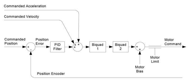
Figure 8: High Level Diagram of PID Calculation Flow
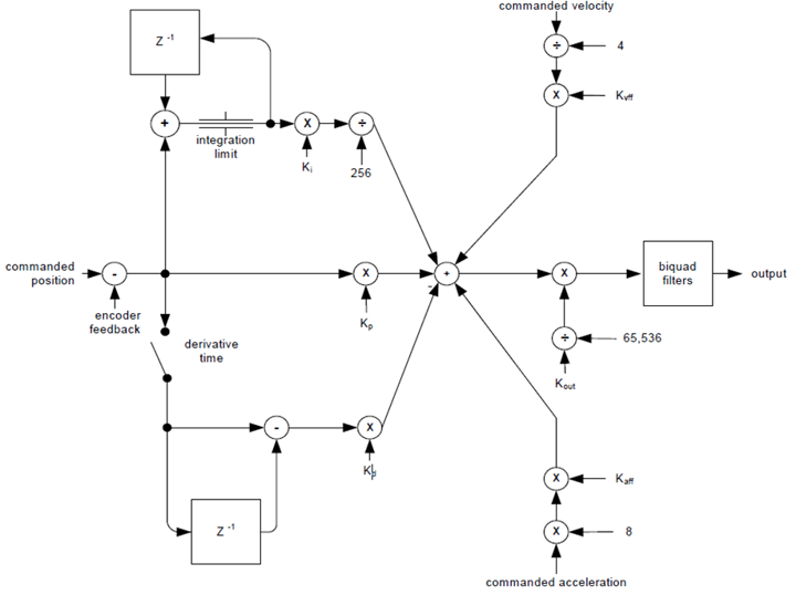
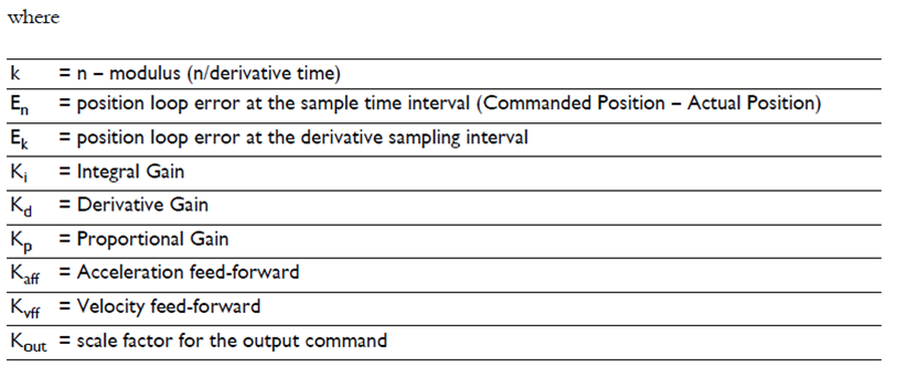
Figure 9: Detailed Calculation Flow of Magellan Position PID Loop
Servo Tracking Window
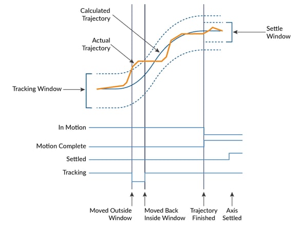
Figure 10: Servo Performance Monitoring
Magellan Motion Control ICs provide a programmable tracking window to monitor servo performance. To initiate this feature the user sets a programmable position error limit within which the axis must remain. Should the axis move outside of the tracking window the Magellan IC can be programmed to report this automatically via hardware signal.
The tracking window is particularly useful for external processes that rely on the motor’s correct tracking of the desired trajectory within a specific range. The tracking window may also be used as an early warning for performance problems that do not yet qualify as a motion error.
Network Communications
Magellan ICs provide three host communication interfaces: parallel, RS232, RS485, and Ethernet.
Parallel
Parallel digital bus interfaces are an easy to use and relatively high speed approach toward communication between a microcontroller and the Magellan IC. 16-bit bi-directional communication is the most common approach, but 8-bit sized word communication is also supported.
Parallel communication packets to/from the microcontroller include a checksum field to ensure data integrity.
Asynchronous Serial
Magellan ICs provide asynchronous serial communications in both point to point and multi-drop format.
The serial port supports baud rates from 1,200 to 460,800 baud. In multi-drop mode the concept of a NodeID is introduced. The voltage levels provided by the Magellan IC’s serial port is UART (TTL) however the interfaces are compatible with RS232 and RS485 standards when the appropriate off-the-shelf interface circuitry is added.
CP (Command Processor) IC Part Numbers
|
Parameter
|
Range
|
Serial 1 Default
|
|
Baud Rate
|
1,200 to 460,800
|
57,600
|
|
Baud Rate
|
None, even, odd
|
None
|
|
Baud Rate
|
5, 6, 7, 8
|
8
|
|
Baud Rate
|
1,2
|
1
|
CAN
Magellan ICs provide CANbus 2.0 communications. CAN provides high communication rates than serial communication schemes, and may be more suitable for noisy, industrial application environments.
The CAN port supports baud rates from 10,000 to 1,000,000 baud. As with serial multi-drop operation CAN networks use the concept of a NodeID to direct traffic to the correct destination node. mode the concept of a NodeID is introduced. The voltage levels provided by the Magellan IC’s serial port is UART (TTL) however the interfaces are compatible with RS232 and RS485 standards when the appropriate off-the-shelf interface circuitry is added.
Settings & default values for the CAN Port
|
Parameter
|
Range
|
Serial 1 Default
|
|
Baud Rate
|
10,00 to 1,000,000
|
20,000
|
|
Baud Rate
|
11-bits
|
n/a
|
Appendix I - Configurations, Parameters, and Performance
|
|
MC58000 Series
(Except MC58113) |
MC55000 Series
|
MC58113 Series
|
|
# of axes
|
1,2,3,4
|
1,2,3,4
|
1+ (primary & aux channel encoder input)
|
|
Motor types supported
|
DC Brush, Brushless DC, step motor
|
Step motor
|
DC Brush, Brushless DC, step motor
|
|
Output format
|
SPI Atlas, PWM, DAC, pulse & direction
|
Pulse & direction
|
SPI Atlas, PWM, DAC, pulse & direction
|
|
Parallel host communication
|
✓
|
✓
|
|
|
Serial host communication
|
✓
|
✓
|
✓
|
|
CAN 2.0B host communication
|
✓
|
✓
|
✓
|
|
SPI host communication
|
|
|
✓
|
|
Incremental encoder input
|
✓
|
✓
|
✓
|
|
Parallel word device input
|
✓
|
✓
|
✓
|
|
Index & Home signals
|
✓
|
✓
|
✓
|
|
Position capture
|
✓
|
✓
|
✓
|
|
Directional limit switches
|
✓
|
✓
|
✓
|
|
PWM output
|
✓
|
|
✓
|
|
SPI Atlas interface
|
✓
|
|
|
|
SPI DAC output
|
✓
|
|
✓
|
|
Pulse & direction output
|
✓
|
✓
|
✓
|
|
Digital current control
|
✓ (with Atlas)
|
|
✓
|
|
Field oriented control
|
✓ (with Atlas)
|
|
✓
|
|
Under/overvoltage sense
|
✓ (with Atlas)
|
|
✓
|
|
12T Current foldback
|
✓ (with Atlas)
|
|
✓
|
|
DC Bus shunt resistor control
|
|
|
✓
|
|
Overtemperature sense
|
✓ (with Atlas)
|
|
✓
|
|
Short circuit sense
|
✓
|
✓
|
✓
|
|
Motor output modes
|
✓
|
✓
|
✓
|
|
Velocity profiling
|
✓
|
✓
|
✓
|
|
S-curve profiling
|
✓
|
✓
|
✓
|
|
Electronic gearing
|
✓
|
✓
|
✓
|
|
On-the-fly changes
|
✓
|
✓
|
✓
|
|
PID position servo loop
|
✓
|
|
✓
|
|
Dual biquad filters
|
✓
|
|
✓
|
|
Dual encoder loop
|
|
|
✓
|
|
Current loop resolution
|
✓ (multi-axis configurations only)
|
|
✓
|
|
Programmable derivative sampling time
|
✓
|
|
✓
|
|
Feedforward (accel & vel)
|
✓
|
|
✓
|
|
Data trace/diagnostics
|
✓
|
✓
|
✓
|
|
Motion error detection
|
✓
|
✓ (with encoder)
|
✓
|
|
Axis settled indicator
|
✓
|
✓ (with encoder)
|
✓
|
|
Analog input
|
✓
|
✓
|
✓
|
|
Programmable bit output
|
✓
|
✓
|
✓
|
|
Software-invertible signals
|
✓
|
✓
|
✓
|
|
User-defined I/O
|
✓
|
✓
|
✓
|
|
Internal Trace Buffer
|
|
|
✓
|
|
External RAM supports
|
✓
|
✓
|
|
|
Multi-chip synchronization
|
✓
|
|
✓
|
|
Chipset configurations
|
MC58420 (4 axes, 2 ICs)
MC58320 (3 axes, 2 ICs) MC58220 (2 axes, 2 ICs) MC58120 (1 axis, 2 ICs) MC58110 (1 axis, 1 IC) |
MC55420 (4 axes, 2 ICs)
MC55320 (3 axes, 2 ICs) MC55220 (2 axes, 2 ICs) MC55120 (1 axis, 2 ICs) MC55110 (1 axis, 1 IC) |
MC51113 (1+ axis, 1 IC)
MC53113 (1+ axis, 1 IC) MC54113 (1+ axis, 1 IC) MC58113 (1+ axis, 1 IC) |
|
IC Package: CP chip
|
MC58x20: 144 pin TQFP
MC58110: 144 pin TQFP |
MC55x20: 144 pin TQFP
MC55110: 144 pin TQFP |
100 pin TQFP
|
|
IC Package: IO chip
|
MC58x20: 100 pin TQFP
MC58110: NA |
MC55x20: 100 pin TQFP
MC55110: NA |
N/A
|
|
Motion control IC developer’s kit p/n’s
|
DK58420
DK58320 DK58220 DK58120 DK58110 |
DK55420
DK55320 DK55220 DK55120 DK55110 |
DK51113
DK53113 DK54113 DK58113 |
Appendix II – MC58000 and MC55000-Series IC Interconnections
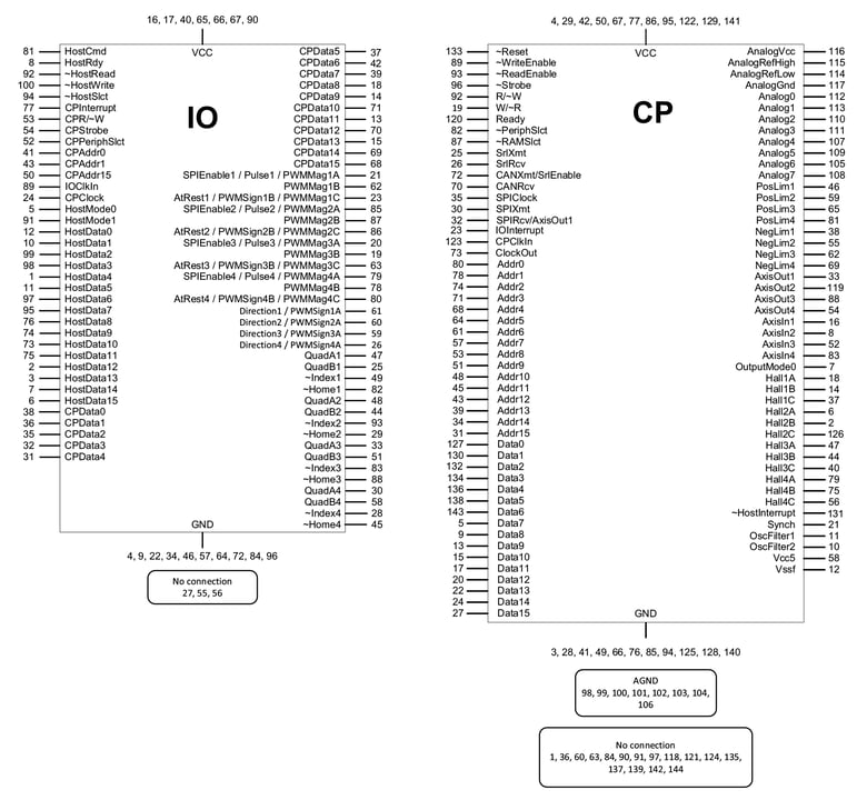
Appendix III – Pinouts
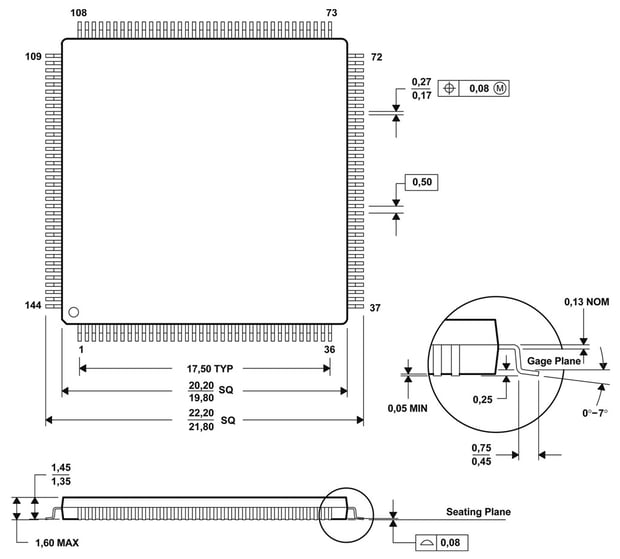
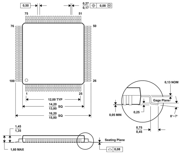
Appendix IV - Physical Characteristics and Mounting Dimensions
Additional Resources
- Magellan MC5x000 Series Motion Control ICs
- Magellan Family of Motion Control IC Datasheet (PDF)
- MC58000 Electrical Specification (PDF)
- MC55000 Electrical Specification (PDF)
- Magellan MC5x000 Developer Kits
- PMD Resource Center