
The Magellan® MC58113 Series of Motion Control ICs are single axis IC members of PMD's Magellan Motion IC Family. These devices are complete chip-based motion controllers. They provide trajectory generation, programmable breakpoints, advanced performance trace, and many related motion control functions.
Depending on the type of motor controlled, they provide servo-loop closure, on-board commutation for Brushless DC motors, and pulse and direction output. Finally, the MC58113-series ICs provide advanced digital current control along with numerous amplifier management features.
The MC58113-series ICs together with other Magellan ICs provide a software-compatible family of dedicated motion control ICs which can handle a large variety of system configurations. Having similar hardware and command architecture enable Magellan ICs to share software commands, so that software written for one may be re-used with another; even though the type of motor may be different.
Available Configurations
There are four different members of the MC58113 family, each representing a different configuration of motor supported.
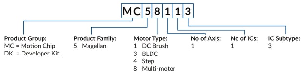
The following table shows the available MC58113 part numbers and associated Developer Kit part number:
|
IC Part Number (P/N)
|
Developer Part Number
|
Motor Type
|
|
MC58113
|
DK58113
|
DC Brush, Brushless DC, step motor
|
|
MC53113
|
DK53113
|
Brushless DC
|
|
MC51113
|
DK5113
|
DC Brush
|
|
MC54113
|
DK4113
|
Step motor
|
Developer Kits
Developer Kits are available for all of the MC58113 Series IC products. Each developer kit includes:
- MC58113 Developer Kit Board
- Pro-Motion Software
- Software Development Kit (SDK) with C-Motion
- Complete Manual Set
- Complete cable and prototyping connector set
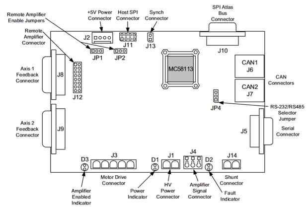
Figure 1: MC58113 Developer Kit
MC58113 Feature List
- Single axis, single IC
- FOC (field oriented control)
- Position, velocity, and torque control
- Incremental encoder quadrature input (up to 25 Mcounts/sec)
- Brushless DC, DC Brush, and step motor control
- Synch pin feature allows multiple axes to be synchronized to <1 μsec
- S-curve, trapezoidal, velocity contouring, and electronic gearing profiles
- Internal motion trace NVRAM for performance optimization
- SPI (Serial Peripheral Interface), serial RS232/485, and CANbus communications
- Overcurrent, over/undervoltage and overtemperature detect
- 5 axes (primary and auxiliary encoder) control
- Directional limit switch, index, and home inputs
- Advanced PID filter with velocity and acceleration feedforward
- Axis settled indicator, tracking window and automatic motion error detection
- High performance current control of each motor phase
- General-purpose analog input
- High/Low switching amplifier control with programmable deadtime and charge pump refresh
- Programmable dual biquad filters
- Velocity, position, and acceleration changes on-the-fly
- Programmable acceleration and deceleration values
- Compact 100-pin TQFP package
- Programmable position loop time from 50 μsec to 1.1 sec
Internal Block Diagram
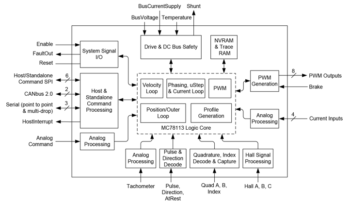
Figure 2: MC58113 Internal Block Diagram
Interconnection Diagram
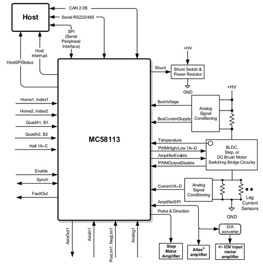
Figure 3: MC58113 Interconnection Diagram
Typical Applications
Position Control of Brushless DC and DC Brush Motors
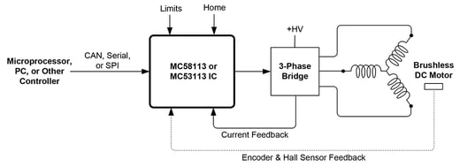
Figure 4: Position Control of Brushless DC and DC Brush Motors
Applications: Laboratory automation, mobile robotics, scientific equipment, spindle control, liquid pumping, industrial automation, general purpose motion control.
In this configuration a MC58113, MC53113, or MC51113 IC receives commands from a host microprocessor, PC, or other controller. The host provided commands, sent via CAN, serial, or SPI, which specify parameters such as the desired trajectory profile, servo PID settings, current gain settings, and other parameters. PWM amplifier control signals are output to a three-phase or single H-bridge located on the same control PCB and current feedback signals from this switching bridge are input directly into the MC58113 series IC. The above diagram shows a Brushless DC motor but similar position control can be provided for DC Brush motors.
Quadrature encoder and Hall-sensor signals can be input for Brushless DC motors however only one of these two is required. For DC Brush motors encoder feedback is required for positioning control.
Position Control of Step Motors
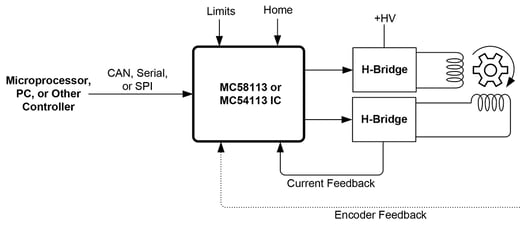
Figure 5: Position Control of Step Motors
Applications: Laboratory automation, mobile robotics, scientific equipment, spindle control, liquid pumping, industrial automation, general purpose motion control.
In this configuration a MC58113 or MC54113 IC receives commands from a host microprocessor, PC, or other controller. The host provided commands, sent via CAN, serial, or SPI, which specify parameters such as the desired trajectory profile, microstepping resolution, current gain settings, and other parameters. PWM amplifier control signals are output to a dual H-bridge amplifier located on the same control PCB and current feedback signals from the switching circuit are input directly back to the MC58113 series IC.
Quadrature encoder signal input is supported but is optional for step motor control.
Position Control of Brushless DC, DC Brush, or Step Motors With Atlas Amplifier
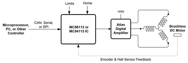
Figure 6: Position Control with Atlas Digital Amplifier
Applications: Laboratory automation, mobile robotics, scientific equipment, spindle control, liquid pumping, industrial automation, general purpose motion control.
In this configuration a MC58113, MC53113, MC51113, or MC54113 IC outputs desired torque commands via an SPI bus connection to an Atlas amplifier located on the same PCB. The Atlas amplifier performs current control and amplification for Brushless DC, DC Brush, or step motors. Three power ranges of Atlas amplifiers are available: 500W, 250W, and 75W.
Other than the approach toward amplification, the control features provided with this configuration are the same as for the previous two configurations.
Position Control of Step Motors Using External Pulse & Direction Amplifier
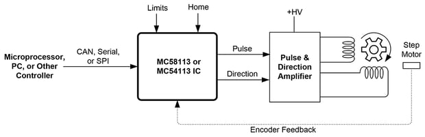
Figure 7: Position Control of Step Motors Using External Pulse & Direction Amplifier
Applications: Laboratory automation, mobile robotics, scientific equipment, spindle control, liquid pumping, industrial automation, general purpose motion control.
In this configuration a MC58113 or MC54113 IC outputs pulse & direction signals to an external amplifier. This amplifier can be located on the same PCB as the MC58113 IC or can be located remotely. The resultant motion may or may not be microstepping depending on the function and control settings of the connected amplifier. Note that this configuration may also be used to drive servo motors if the amplifier used is capable of performing position servo control and if it accepts a pulse & direction command data stream.
Other than the approach toward amplification the control features provided with this configuration are the same as for the previous configurations.
CAM Profile Control of Brushless DC, DC Brush, or Step Motors
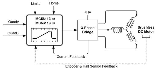
Figure 8: CAM Profile Control of Brushless DC, DC Brush, or Step Motors
Applications: Textile, winding equipment, key cutting, packaging equipment, laboratory automation, mobile robotics, thin film handling, liquid pumping.
In this configuration a MC58113, MC53113, MC51113, or MC54113 IC inputs a quadrature position data stream from an external encoder and uses it as the master rate command for execution of a cam or electronic gear profile. Prior to profile operation the cam profile shape is stored by the user into the MC58113. Execution of camming functions and of other complex shapes is enabled via the Magellan's User Defined Profile Mode, which is available in a special version of the MC58113. For more information on User Defined Profile Mode contact your local PMD representative.
The above diagram shows a Brushless DC motor but similar control can be provided for DC Brush and step motors.
Closed Loop Operation of Step Motors
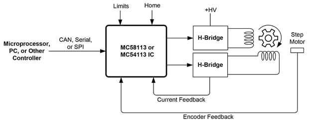
Figure 9: Closed Loop Operation of Step Motors
Applications: Laboratory automation, textile equipment, high acceleration applications, electronics manufacturing equipment, die bonding, industrial automation.
In this configuration a MC58113 or MC54113 IC executes closed loop control (also called servo stepper operation) of a step motor. In this control mode the step motor is operated as a servo motor, using commutation and a variable torque command rather than traditional microstepping control. Relative to normal step motor operation closed loop control may provide smoother motion, less noise, higher acceleration, and eliminate lost steps.
Quadrature encoder input is required for closed loop step motor operation. Other than the approach toward position and torque control, the control features provided with this configuration are the same as for the previous configurations.
Multi-Axis Control of Brushless DC, DC Brush, or Step Motors
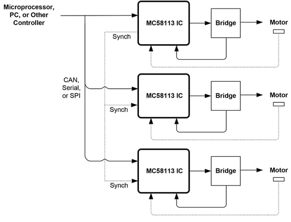
Figure 10: Multi-Axis Control of Brushless DC, DC Brush, or Step Motors
Applications: Laboratory automation, scientific equipment, 3D printing, multi-dimensional contouring, industrial automation, general purpose motion control.
In this configuration MC58113, MC53113, MC51113 or MC54113 ICs are connected in a multi-axis configuration. A single host such as a microprocessor, PC, or other controller sends commands to the connected MC58113 series ICs via CAN, serial (RS485), or SPI. For applications which require tight synchronization MC58113 series ICs support a hardware Synch signal which allows sub-microsecond synchronization of all connected axes.
Depending on the application, standard Magellan profile modes such as trapezoidal, S-curve, or velocity contouring profiles may be used. Alternatively, to perform multi-dimensional synchronized contouring a special version of MC58113 series ICs that supports User Defined Profile Mode may be used. For more information on User Defined Profile Mode contact your local PMD representative.
MC58113 Key Product Features
Advanced Instruction Set
Here is a list of some of the functions provided by the MC58113 Series Motion Control ICs:
- Profile generation
- Quadrature encoder processing and index capture
- DC Brush and Brushless DC servo loop closure
- Breakpoint processing
- Trace
- Motion error detection, tracking windows, and axis-settled indicator
- Limit switch processing
- Current control
Magellan instructions are encoded in packets, which are sent to and from the Magellan Motion Control IC. The Magellan processes these packets perform requested functions, and returns requested data. Generally speaking, each command packet has its own C-Motion command associated with it.
Example Magellan Instructions
The Magellan instruction set is flexible and powerful. The following very simple example, which sets up and executes a trapezoidal profile, illustrates just a small part of the overall command set. In addition, this small sequence shows the look and feel of C-Motion, PMD’s C-language callable motion interface that handles communications to and from all machine controller board resources.
|
PMDSetProfileMode(&hAxis1, PMDProfileTrapezoidal);
|
// set profile mode to trapezoidal for axis 1
|
|
PMDSetPosition(&hAxis1, 12345);
|
// load a destination position for axis 1
|
|
PMDSetVelocity(&hAxis1, 223344)
|
// load a velocity for axis 1
|
|
PMDSetAcceleration(&hAxis1, 1000)
|
// load an acceleration for axis 1
|
|
PMDSetDeceleration(&hAxis1, 2000)
|
// load a deceleration for axis 1
|
|
PMDUpdate(&hAxis1);
|
// initiate the move
|
hAxis1 is a handle to a structure known as a PMDAxisHandle. There are several different C-Motion structures, and in general, they are used to make accessing the MC58113 ICs simpler and more flexible. In particular, by developing code with C-Motion, it is very easy to change the physical location of a PMD axis without any changes to the developed C-Motion code sequences. This is called axis virtualization and is a powerful feature of the C-Motion/Magellan IC system.
Seven-Segment S-Curve Profiling
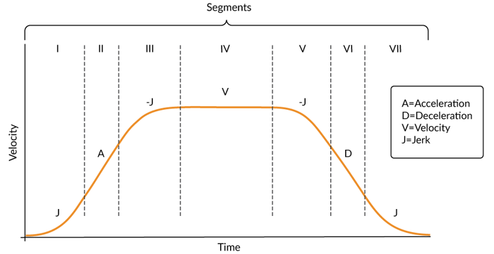
Figure 11: S-curve Profile
While trapezoidal profiles are very common in motion control, the S-curve profile is actually the workhorse for point to point motion because of its greater ability to control the amount of vibrational energy injected into the load. S-curve profiles add a limit to the rate of change of acceleration to the trapezoidal profile. This parameter, known as jerk, specifies the maximum change in acceleration per unit time.
Figure 11 shows a typical S-curve profile. In Segment I, the S-curve profile drives the axis at the specified jerk (J) until the maximum acceleration (A) is reached. The axis continues to accelerate linearly (jerk = 0) through Segment II. The profile then applies the negative value of the jerk to reduce acceleration to 0 during Segment III. The axis is now at maximum velocity (V), at which it continues through Segment IV. The profile will then decelerate in a manner similar to the acceleration stage, using the jerk value first to reach the maximum deceleration (D) and then to bring the axis to a halt at the destination.
Servo Tracking Window
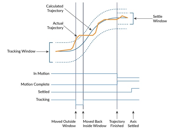
Figure 12: Servo Performance Monitoring
The MC58113 Motion Control ICs provide a programmable tracking window to monitor servo performance. To initiate this feature the user sets a programmable position error limit within which the axis must remain. Should the axis move outside of the tracking window the Magellan IC can be programmed to report this automatically via hardware signal.
The tracking window is particularly useful for external processes that rely on the motor’s correct tracking of the desired trajectory within a specific range. The tracking window may also be used as an early warning for performance problems that do not yet qualify as a motion error.
High Efficiency Digital Switching Motor Amplifier Control
MC58113 Series ICs provide control of an on-PCB digital power stage with PWM (Pulse Width Modulation) control and leg current feedback. A slightly different configuration is used for each motor type:
- DC Brush motors are driven with an H-Bridge consisting of 4 switches.
- Brushless DC motors are driven with a 3-phase bridge consisting of 6 switches.
- Step motors are driven with two H-Bridges, one for each phase, for a total of 8 switches.
The use of 3-phase and H-Bridge topologies provides full 4-quadrant operation.
MC58113 ICs use an advanced PWM switching scheme that minimizes the ripple current on the motor windings while maximizing the current loop performance. The PWM frequency is selectable between 20 kHz and 80 kHz to cover a broad range of motor inductance. The fundamental frequency of the ripple current is at twice the PWM frequency and well out of the audible range in all cases.
A representative diagram of the switch and current sense configuration is shown in Figure 12. The diagram shown is for Brushless DC motors, the configuration will be somewhat different for DC Brush and step motors.
In addition to highly efficient and powerful motor drive capacity the MC58113 ICs provide several important amplifier and DC voltage related safety features including over voltage, under voltage, overcurrent, over temperature, and I2T control for precise control of heating in the actuator and motor being driven.
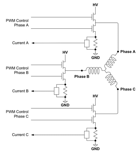
Figure 13: Brushless DC Motor Bridge Configuration
Appendix I - Configurations, Parameters, and Performance
|
Profile modes
|
S-curve point-to-point
|
Position, velocity, acceleration, deceleration, jerk
|
|
|
Trapezoidal point-to-point
|
Position, velocity, acceleration, deceleration
|
|
|
Velocity-contouring
|
Velocity, acceleration, and deceleration parameters
|
|
|
Electronic gear
|
Encoder input, pulse & direction input, or trajectory position of one axis used to drive a second axis. Master and slave axes and gear ratio parameters
|
|
Current control modes
|
A/B
|
Digital loop provides active current control utilizing leg current analog input
|
|
|
FOC
|
Field oriented control loop provides active current control utilizing leg current analog input
|
|
|
Third leg floating
|
Hall-based mode drives two of three legs with the third leg floating
|
|
|
Current loop off
|
Voltage mode control, no current feedback used
|
|
Communication modes
|
SPI (Serial Peripheral Interface) with 16-bit command word size
Point to point asynchronous serial Multi-drop asynchronous serial CAN bus 2.0B |
|
|
Host SPI frequency range
|
1.0 MHz - 10.0 MHz
|
|
|
Serial port baud rate range
|
1,200 baud to 460,800 baud (1,200, 2,400, 9,600, 19,200, 57,600, 115,200, 230,400, 460,800)
|
|
|
CAN port transmission rate range
|
10,000 baud to 1,000,000 baud (10,000, 20,000, 50,000, 125,000, 250,000, 500,000, 800,000, 1,000,000)
|
|
|
Position range
|
-2,147,483,648 to +2,147,483,647 counts or steps
|
|
|
Velocity range |
-32,768 to +32,767 counts or steps per cycle with a resolution of 1/65,536 counts or steps per cycle
|
|
|
Acceleration and deceleration ranges
|
0 to +32,767 counts or steps per cycle2 with a resolution of 1/65,536 counts or steps per cycle2
|
|
|
Jerk range
|
0 to ½ counts or steps per cycle3 with a resolution of 1/4,294,967,296 counts or steps per cycle3
|
|
|
Electronic gear ratio range
|
-32,768 to +32,767 with a resolution of 1/65,536 (negative and positive direction)
|
|
|
Filter modes
|
Scalable PID + velocity feedforward + acceleration feedforward + bias. Also includes integration limit, settable derivative sampling time, output motor command limiting and two bi-quad filters.
Dual encoder feedback mode where the auxiliary encoder is used for backlash compensation |
|
|
Filter parameter resolution
|
16 bits
|
|
|
Position error
|
32 bits
|
|
|
Position error tracking
|
Motion error window
|
Allows axis to be stopped upon exceeding programmable window
|
|
|
Tracking window
|
Allows flag to be set if position error is within a programmable position window
|
|
|
Axis settled
|
Allows flag to be set if position error is within programmable position window for a programmable amount of time after trajectory motion is complete
|
|
Motor output modes
|
PWM
|
20 kHz, 40 kHz, 80 kHz
|
|
|
SPI DAC
|
16 bits
|
|
|
Pulse and direction
|
1.0 Mpulses/sec maximum
|
|
|
SPI Atlas
|
Four-signal SPI interface with 16-bit packet commands and SPI Atlas protocol
|
|
Commutation rate
|
19.53 kHz
|
|
|
Current loop rate
|
19.53 kHz
|
|
|
Current measurement resolution
|
12 bits
|
|
|
PWM resolution
|
1:2,048 @ 20 kHz 1:1,024 @ 40 kHz 1:512 @ 80 kHz
|
|
|
Current loop type
|
P, I (proportional integral) with integral limit
|
|
|
Current loop resolution
|
16 bits
|
|
|
Drive safety functions
|
Over current detect, over temperature detect, over voltage detect, under voltage detect, i2t current foldback
|
|
|
Output limiting
|
Energy, current, and voltage limit
|
|
|
NVRAM storage size
|
1,024 16-bit words
|
|
|
Microstepping waveform
|
HostCAN (CAN/SPI host interface unit Sinusoidal)
|
|
|
Microsteps per full step
|
1 to 256
|
|
|
Maximum encoder rate
|
25 Mcounts/sec
|
|
|
Hall sensor inputs
|
3 Hall effect inputs
|
|
|
Cycle time range
|
51.2 microseconds to 1.048576 seconds
|
|
|
Multi-chip synchronization
|
<1 μSec difference between master and slave servo cycle
|
|
|
Limit switches
|
1 for each direction of trave
|
|
|
Position-capture triggers
|
Index and Home signals
|
|
|
Other digital signals
|
1 AxisIn signal, 1 AxisOut signal
|
|
|
Software-invertible signals
|
Quad A, Quad B, Index, Home, AxisIn, AxisOut, PositiveLimit, NegativeLimit, HallA, HallB, HallC (all individually programmable), Pulse, Direction
|
|
|
General purpose analog input
|
1 12-bit analog input
|
|
|
RAM internal memory
|
16,380 words
|
|
|
Maximum number of simultaneous trace variables
|
4
|
|
|
Number of traceable variables
|
73
|
|
Appendix II - Physical Characteristics and Mounting Dimensions
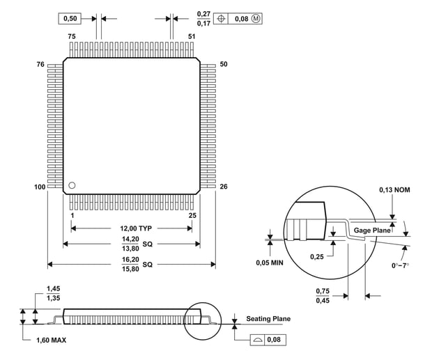
Figure 14: Physical Characteristics and Mounting Dimensions
Appendix III - Pinouts
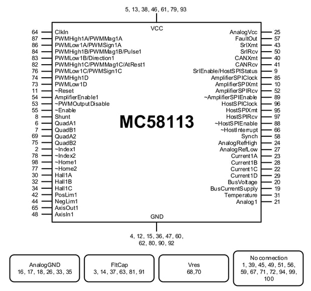
Figure 15: MC58113 Pinouts
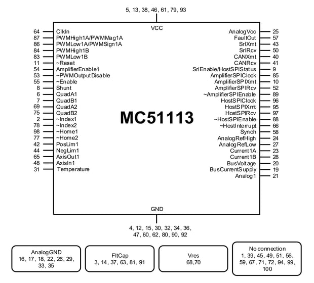
Figure 16: MC51113 Pinouts
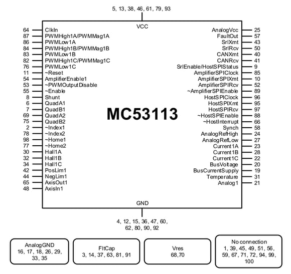
Figure 17: MC53113 Pinouts
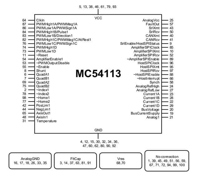
Figure 18: MC54113 Pinouts
Additional Resources
- Magellan MC58113 Series Motion Control ICs
- Magellan MC58113 IC Datasheet (PDF)
- MC58113 Electrical Specification (PDF)
- Magellan MC58113 Developer Kits
- PMD Resource Center