
Conventional step “current chopper” drives result in a large amount of step motor noise, needless motor heating, and consume more current. A digital current loop will result in significantly quieter and lower temperature motor operation which is beneficial in many applications. This article details how a digital current loop will result in a significantly quieter, faster running, and lower temperature motor operation which is beneficial in many applications.
Experiment background
Step motors are present in approximately half of all motion control solutions. As compared to servo motors, less expensive step motors are often used in lower speed applications where the dynamic loading is predictable and minimal. There is no reason to pay the higher price of a servo motor with position feedback if the application requirements can be achieved with a step motor. If the step motor performance needs improving, sometimes a “closed-loop” stepper system will be implemented by adding a position encoder to the step motor. While this solution will increase the dynamic response of the motor, it has several disadvantages:
- Additional cost of encoder
- Additional wires for encoder
- Additional risk of component failure
- Extra time spent on system commissioning to tune the closed loop response
To increase the performance of a step motor, an alternative is to optimize the behavior of the current control method without requiring the addition of a position feedback encoder to the system. Current control is the responsibility of the motor amplifier (drive stage) and therefore system improvements can be made by selecting a digital amplifier with improved winding current regulation.
Stable control of a step motor requires control of the current in the motor windings. Historically this current is controlled with a “current chopper”. In this case, the full supply voltage is applied to the motor windings until the current reaches a predefined comparison value. After reaching this set value the voltage is removed from the motor winding for a fixed amount of time as a result of which the current will decrease. Typically, the user has some control over the comparison value and the “off” time.
Performance Motion Devices employs an improved current control algorithm which applies a proportional voltage calculated from a PI (Proportional/Integral) current control loop. The implementation of a Pulse Width Modulation (PWM) scheme means that the effective voltage being applied to the motor winding is some fraction of the bus voltage. The result is a set of current waveforms in the two motor phases which are both much closer to the desired currents and much smoother (Figure 2). The increase in accuracy is especially notable when the current is crossing zero, where legacy current chopper drives do a poor job of regulation.
The improvement in the current waveform has several benefits at the system level. The most noticeable will be a reduction in audible noise which is a result of reduced vibration in the motor and the load attached to the motor. Any vibration present in the system represents wasted mechanical energy and increased motor temperature. Still, another benefit is that the reduction in vibration implies there is more energy available for the desired mechanical response (acceleration and deceleration) and less energy is wasted on heating the motor.
Experimental results
An experimental system comprised of a step motor and an amplifier/drive stage was created for the purposes of collecting comparative data. One setup utilized a legacy current chopper drive and another utilized Performance Motion Devices Developer Kit DK58113 which uses a PI digital current loop.
One set of comparison data represents a test where the unloaded 24V step motor is commanded to spin as fast as possible without losing steps (Vmax). The other dataset represents the noise and steady state temperature when running the motor at nominal speed/torque values (dBnom, Tnom).
As can be seen from the data, the Performance Motion Devices digital current loop is able to drive the motor 20% faster with greater than 20dB lower noise and a significantly lower operating current than the conventional chopper drive. Additional data was collected using a different step motor designed for high-speed operation.
| Control Board | Vmax (rps) | Vnom (rps) | DBnom | Tnom(°C) |
| DK58113 from PMD | 10.25 | 7.0 | 52.8 | 34.6 |
| Current Chopper | 8.1 | 7.0 | 73.2 | 42 |
As can be seen from the data, the Performance Motion Devices digital current loop is able to drive the motor 20% faster with greater than 20dB lower noise and a significantly lower operating current than the conventional chopper drive. Additional data was collected using a different step motor designed for high-speed operation.
| Control Board | Vmax (rps) |
| DK58113 from PMD | 42.9 |
| Current Chopper | 38.2 |
Again, the digital current loop significantly outperforms the chopper drive.
The experiments above represent operational behavior during continuous rotation. Many times the step motor will drive a linear load within a fixed positional range. The rotary-to-linear translation is typically achieved with a belt drive or a lead screw. The video below demonstrates a linear stage driven with a lead screw and step motor. In the first video segment a conventional current chopping drive is being used and in the next segment, a Performance Motion Devices' DK58113 drive with Proportional Integral (PI) digital current loop control is utilized.
- Watch Video: Step Motor Noise Comparison
The reason the current loop operation outperforms the current chopper is related to the shape of the current waveform in the motor winding. Two specific properties of the waveform can be analyzed in order to understand where the relevant differences are between the digital current loop and current chopper waveforms.
The smoothest operation of a step motor results from generating a sinusoidal current waveform in the windings. A smoother sinusoid will result in smoother motion. Both drive techniques employ the use of a “switching” voltage on the motor windings. The switching event produces a “ringing” or “ripple” in the current waveform which is a deviation from the desired shape. This deviation is wasted energy which causes excessive motor heating. The amount of wasted energy scales with the amplitude of the ringing. Figure 1 demonstrates the shape and current ripple resulting from the use of the current chopper drive. In Figures 1a and 2a, a sine wave has been over-laid onto the waveforms so as to better show how the waveform approaches a pure sine function. Figure 1b is generated by zooming on a small section of the waveform in 1a.
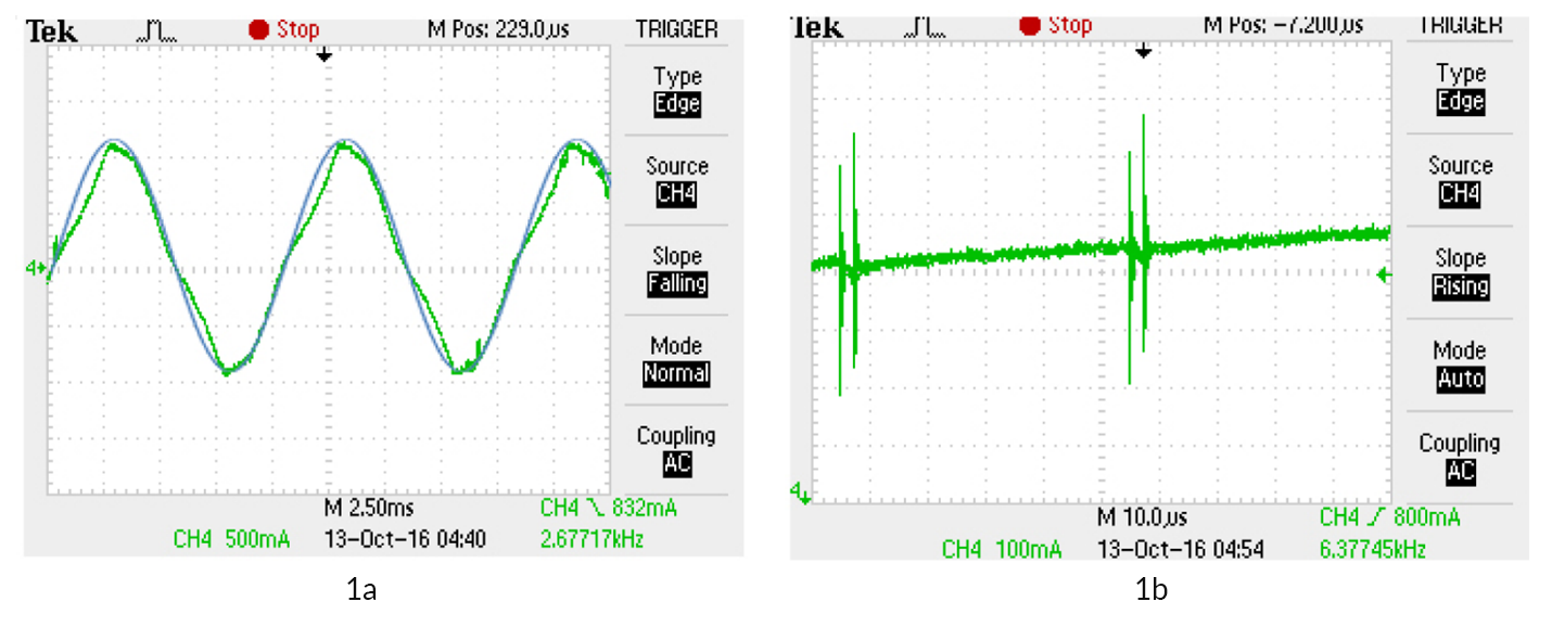
Figure 1: Current Chopper Waveform
Figure 2 demonstrates the waveform when running the same motor under the same motion kinematic conditions using Performance Motion Devices’ PI current loop technology.
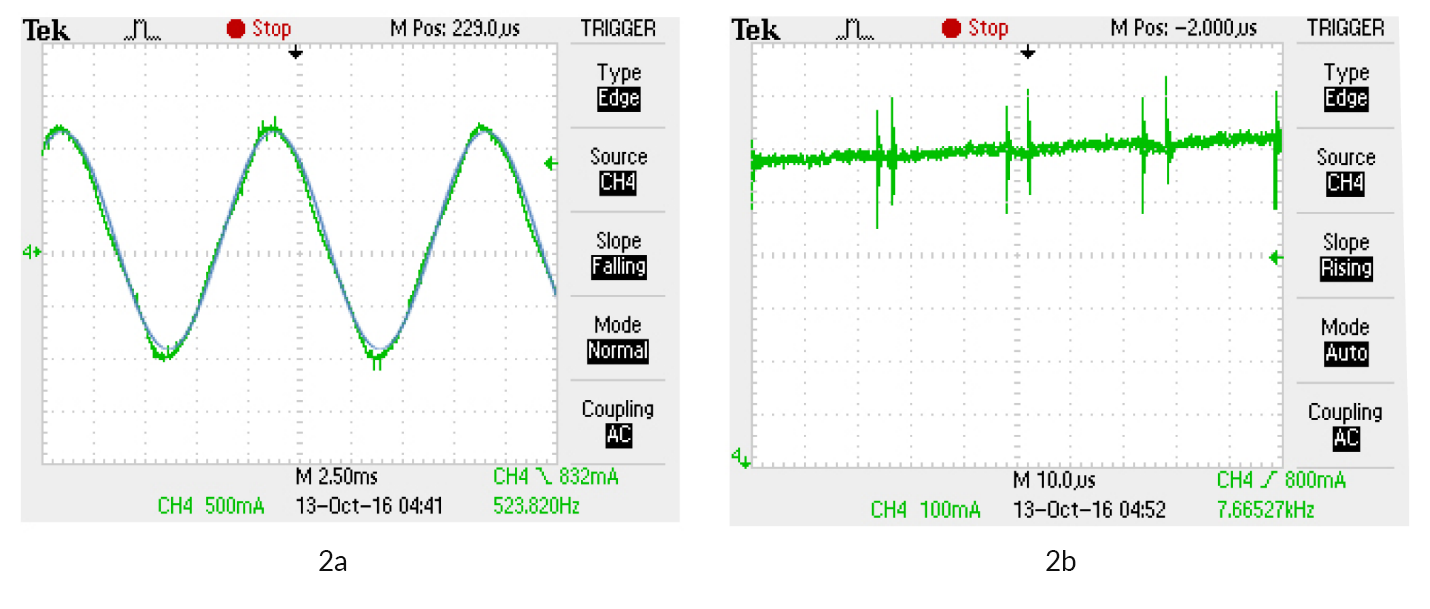
Figure 2: PMD Current Loop Waveform
When comparing Figure 1a to 2a it can be observed that the waveform in Figure 2a has a much smoother sinusoid. A comparison to a sine wave in Figure 1a shows a much poorer correlation of the actual waveform to the sine waveform, and particularly during the latter half of the rise and fall of the motor current, whereas the correlation to a sine wave in Figure 2a shows that the PMD current loop approach is a significantly better match to the ideal sine wave function. Furthermore, the amplitude of current ripple in Figure 2b is half that of Figure 1b. The frequency of the ripple is faster in Figure 1b since the PMD digital current loop, running at 20 kHz, will switch the voltage faster and more periodically. The switching frequency of the current chopper varies, as it depends on how quickly the current transient reaches the comparison value.
You may also be interested in: Motion Kinematics
Conclusion on how to reduce step motor noise
It is clear that conventional step “current chopper” drives result in a large amount of step motor noise, needless motor heating, and consume more current. A digital current loop will result in significantly quieter and lower temperature motor operation which is beneficial in many applications such as laboratory instruments, medical equipment, security camera operation and 3D printers.
As mentioned above the controller will use the available bus voltage to regulate the current. Many step motors are required to operate at high speeds resulting in the presence of a large back EMF Voltage. The back EMF voltage may be so large that it makes regulation of the motor current at its nominal value impossible. This is referred to as “voltage limited” operation and the controller is now tasked with using whatever voltage potential is available to create as much current as possible even though it will inevitably fall short of the rated (or commanded) current. Watch for an upcoming article to learn about control techniques for high speed and voltage limited operation!
You may also be interested in: Motion Kinematics
PMD Products that Provide High Performance Current Control for Step Motors
PMD has been producing ICs that provide advanced motion control of DC Brush and Brushless DC motors for more than twenty-five years. Since that time, we have also embedded these ICs into plug and play modules and boards. While different in packaging, all PMD products are controlled by C-Motion, our easy to use motion control language and are ideal for use in medical, laboratory, semiconductor, robotic, and industrial motion control applications.
MC58113 Series IC
The MC58113 series of ICs are core members of PMD's popular Magellan Motion Control IC Family and provide advanced position control for BLDC, DC Brush, and step motors alike. Standard features include S-curve profiling, FOC (Field Oriented Control), high/low switch signal control, direct encoder & pulse & direction input, and much more. Whether used for laboratory automation, pump control, pointing systems, or general-purpose automation, the MC58113 family of chips are the ideal solution for your next machine design.
Learn more >>

Prodigy/CME Machine-Controller
The Juno family of velocity & torque control ICs are perfect for building your own low cost, high performance pump controller. Juno ICs feature advanced velocity control with dual biquad, torque mapping, deadband filters, profiling, FOC (Field Oriented Control), and more. Available for Brushless DC, DC Brush, and step motors, these compact ICs are an ideal solution for your next liquid pumping design.
Learn more >>
Atlas Digital Amplifiers
Atlas Digital Amplifiers are compact single-axis amplifiers that provide high-performance torque control for Brushless DC, DC Brush, and Step motors. Atlas amplifiers come in both a vertical and horizontal mounting configuration and are available in three power ranges: 75W, 250W, and 500W. They are used for direct control of motor torque or in conjunction with higher-level motion controllers providing position or velocity control functions.
Learn more >>
ION/CME N-Series Digital Drives
N-Series ION Digital Drive combine a single axis Magellan IC and a high performance digital amplifier into an ultra-compact PCB-mountable package. In addition to advanced servo and step motor control, N-Series IONs provide S-curve point to point profiling, field oriented control, downloadable user code, general purpose digital and analog I/O, and much more. With these all-in-one devices building a custom controller board is a snap, requiring you to create just a simple 2 or 4-layer interconnect board.
Learn more >>
You may also be interested in:
- Keep Your Step Motor Position with A Closed Loop Motion Control System
- Motion Control Goes Small
- S-Curves Profiles - A Deep Dive
- Feedforward in Motion Control - Vital for Improving Positioning Accuracy
- Field Oriented Control Deep Dive