Brushless DC motors (BLDC motors) are widely used in modern motion systems because they offer high efficiency, high torque density, and long operational life. However, achieving smooth, accurate, and reliable motion from a BLDC motor depends almost entirely on how the motor is controlled.
In this article, we take a system-level view of how to control brushless motors. We begin with the fundamentals of BLDC operation, move through commutation techniques, and then explain how advanced control methods such as Field Oriented Control (FOC) enable higher performance. We close by examining how control architecture choices affect accuracy, tuning effort, and long-term system behavior.
This progression reflects how most real-world motion systems are designed: from basic operation to refined performance.
| |
What Makes Brushless Motors Different?
At a high level, controlling a BLDC motor means answering one question continuously:
Which motor phases should be energized, and by how much, at this instant in time?
Several approaches exist, each with different performance tradeoffs.
Trapezoidal (Six-Step) Commutation
Trapezoidal commutation energizes two of the three motor phases at a time while the third is left floating. Rotor position is typically derived from Hall-effect sensors or inferred from back-EMF measurements.
This method is simple and cost-effective, but it produces torque ripple and acoustic noise, particularly at low speeds. For applications where smoothness and precision are not critical, trapezoidal control can be sufficient.
Sinusoidal Commutation
Sinusoidal commutation improves upon trapezoidal control by applying smoothly varying current waveforms to the motor phases based on the rotor’s electrical position. Rotor position is typically provided by an encoder, resolver, or estimated using observer-based methods, allowing the controller to align phase currents sinusoidally with the rotor magnetic field.
By shaping phase currents as sine waves rather than discrete steps, torque ripple is reduced and motion becomes noticeably smoother, particularly at low speeds.
However, sinusoidal commutation still controls each motor phase directly rather than explicitly controlling torque and magnetic flux as separate quantities. While rotor position is known and used to shape the current waveforms, torque production remains indirectly coupled to the motor’s magnetic characteristics and phase interactions. As a result, variations in motor parameters or operating conditions can still influence torque linearity and dynamic response.
Field Oriented Control (FOC)
Field Oriented Control represents a fundamental shift in how brushless motors are controlled.
Instead of managing phase currents directly, FOC transforms the three-phase motor currents into a rotating reference frame aligned with the rotor’s magnetic field. In this reference frame, current is separated into two orthogonal components:
- Direct-axis (d-axis) current, which controls magnetic flux
- Quadrature-axis (q-axis) current, which directly produces torque
By controlling these components independently, FOC allows torque to be regulated with exceptional precision. The result is:
- Near-zero torque ripple
- High efficiency across a wide speed range
- Excellent low-speed and zero-speed performance
- Predictable dynamic response under changing loads
Because of these advantages, FOC is widely used in high-performance servo systems and precision motion applications.
System-Level Architecture: Where Performance Is Really Determined
Once Field Oriented Control is selected, the next — and often underestimated — decision is how the control system itself is architected.
In a complete BLDC control system, up to three control loops operate simultaneously:
1. Current (torque) loop
2. Velocity loop
3. Position loop
The placement, bandwidth, and interaction of these loops determine how the system behaves under real operating conditions.
In a well-architected system, the current loop runs at the highest rate, tightly regulating motor torque by directly controlling winding current. This loop shields higher-level control loops from electrical dynamics, motor inductance, and supply variations.
Above the current loop sits the velocity loop, which regulates motor speed by commanding torque changes. Finally, the position loop generates velocity commands based on trajectory and position error.
When these loops are tightly integrated and synchronized, the system behaves predictably:
- Torque commands translate linearly into motion
- Mechanical resonance is easier to manage
- Tuning effort is reduced because each loop operates in a well-defined role
In contrast, architectures that separate these loops across loosely coupled components often require more aggressive tuning and compensation to achieve the same results.
From a system perspective, this integration is what allows advanced control techniques — such as feedforward compensation and motion profiling — to work as intended rather than fighting downstream dynamics.
Closed-Loop Control and Feedback Devices
Accurate BLDC control depends on reliable rotor position feedback. Common feedback devices include:
- Incremental encoders
- Absolute encoders
- Resolvers
High-resolution feedback improves commutation accuracy and allows tighter control loop gains. In FOC-based systems, rotor position accuracy directly affects torque linearity and efficiency.
Feedback quality becomes especially important in applications that demand:
- Smooth low-speed motion
- High acceleration and deceleration
- Precise positioning under varying loads
Tuning and Performance Optimization
Even with a well-designed architecture, achieving optimal performance requires proper tuning of the control loops.
The tuning process typically progresses inward to outward:
1. Tune the current loop for fast, stable torque response
2. Tune the velocity loop to manage inertia and damping
3. Tune the position loop for accuracy and settling behavior
Modern motion systems often provide diagnostic tools that allow engineers to observe internal variables — such as current, velocity error, and position error — in real time. These insights are essential for validating assumptions and refining system performance.
| |
Motor Selection and Control Strategy Alignment
Not all motors benefit equally from advanced control techniques. Factors such as motor construction, inductance, and feedback resolution influence achievable performance.
In some cases, alternatives such as closed-loop steppers or lower-cost BLDC configurations may provide sufficient performance with reduced system complexity. Understanding where each motor type fits helps ensure the control strategy aligns with application requirements rather than exceeding them unnecessarily.
Bringing It All Together
Controlling a brushless motor is not just about choosing a commutation method. It is about designing a control system where electrical, mechanical, and software elements work together coherently.
Field Oriented Control provides the foundation for high-performance BLDC operation, but it is the system-level architecture — the integration of current, velocity, and position control — that ultimately determines how well theory translates into real motion.
When these elements are aligned, engineers gain motion systems that are smoother, more accurate, easier to tune, and more robust over the lifetime of the machine.
PMD Products That Control Brushless Motors
PMD has been producing ICs that provide advanced motion control of DC Brush, Brushless DC, and stepper motors for more than twenty-five years. Since that time, we have also embedded these ICs into plug and play modules and motion control boards. While different in packaging, all of these products are controlled by C-Motion, PMD's easy to use motion control language and are ideal for use in medical, laboratory, semiconductor, robotic, and industrial motion control applications.
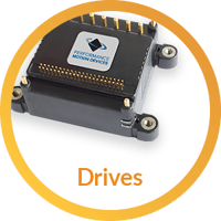
ION/CME N-Series Drives
ION®/CME N-Series Drives are high performance intelligent drives in an ultra-compact PCB-mountable package. In addition to advanced servo and stepper motor control, N-Series IONs provide s-curve point to point profiling, field oriented control, downloadable user code, general purpose digital and analog I/O, and much more. These all-in-one devices make building your next machine controller a snap.
Learn more >>

MC58113 Series ICs
The MC58113 series of ICs are part of PMD's popular Magellan Motion Control IC Family and provide advanced position control for stepper, Brushless DC, and DC Brush motors alike. Standard features include FOC (Field Oriented Control), trapezoidal & s-curve profiling, direct encoder and pulse & direction input, and much more. The MC58113 family of ICs are an ideal solution for your next machine design project.
Learn more >>
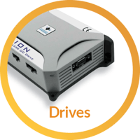
ION 500 & 3000 Drives
ION 500 and 3000 Drives are high performance intelligent drives in a compact cable-connected package. In addition to advanced servo motor control, IONs provide s-curve point to point moves, i2T power management, downloadable user code, and a range of safety functions including over current, over voltage, and over temperature detect. IONs are easy to use plug and play devices that will get your application up and running in a snap.
Learn more >>

Prodigy/CME Machine Controller
Prodigy®/CME Machine Controller boards provide high-performance motion control for medical, scientific, automation, industrial, and robotic applications. Available in 1, 2, 3, and 4-axis configurations, these boards support DC Brush, Brushless DC, and stepper motors and allow user-written C-language code to be downloaded and run directly on the board. The Prodigy/CME Machine-Controller has on-board Atlas amplifiers that eliminate the need for external amplifiers.
Learn more >>
You may also be interested in:
- PMD Positioning Motion Control ICs Applications Summary (Article)
- OLogic Case Study - Robotics Design Firm (Case Study)
- ION/CME N-Series Drive Applications Summary (Article)
- Build vs. Buy of a Three Axis Motion Controller (Article)