
 QuickBytes
 For further analysis, read the full article: Field-Oriented Control (FOC) - A Deep Dive For further analysis, read the full article: Field-Oriented Control (FOC) - A Deep Dive |
Engineering Context: Why Servo Stability Matters
Servo instability is one of the most common performance limitations in modern motion systems.
It often appears as:
- Oscillation and overshoot
- Audible whining or buzzing
- Vibration at specific speeds
- Position hunting during low-speed motion
- Unstable settling after direction changes
- Positioning error in precision systems
These issues are especially critical in:
- Robotics systems
- Semiconductor motion stages
- Precision automation equipment
- Medical motion devices
- Multi-axis coordinated systems
Key Insight
— Servo instability is often treated as a tuning problem — but the root cause is frequently poor torque control.
That is why Field-Oriented Control (FOC) has become foundational in high-performance BLDC servo systems.
What Is Field-Oriented Control (FOC)?
Field-oriented control servo stability is achieved by precisely regulating motor current and torque within a rotating reference frame aligned to rotor position.
FOC separates motor current into:
- d-axis current (flux control)
- q-axis current (torque control)
This allows the controller to regulate torque continuously instead of relying on abrupt phase switching.
Why it matters
Compared to traditional commutation methods, FOC improves:
- Torque smoothness
- Current loop stability
- High-speed motion quality
- Servo responsiveness
- Torque ripple reduction
Key Motion Control Terms
Current loop bandwidth
The speed at which the controller regulates motor current in response to commanded torque changes.
d-q current loop tuning
The process of adjusting the proportional and integral gains used to regulate d-axis and q-axis currents in an FOC system.
Torque ripple
Periodic variation in motor torque caused by commutation effects, current distortion, or motor geometry.
Servo oscillation
Repeated instability in motor position, velocity, or torque caused by insufficient damping or unstable control loops.
Deterministic motion control
A motion architecture where loop execution timing remains predictable and synchronized.
What Causes Servo Instability in BLDC Systems?
Most BLDC servo systems use nested control loops:
|
Loop |
Function |
|
Position loop |
Trajectory tracking |
|
Velocity loop |
Speed regulation |
|
Current loop |
Torque generation |
Key Insight
— Every outer loop depends on the current loop beneath it.
If the current loop becomes unstable:
- Torque output oscillates
- Velocity regulation degrades
- Position tracking errors increase
- Mechanical resonance may be excited
This is why current loop stability is the foundation of servo performance.
How Does FOC Improve Servo Stability?
FOC improves stability by:
- smoothing torque production
- improving current regulation
- reducing disturbance sensitivity
- Improved high-speed motion
1. FOC Reduces Torque Ripple
Traditional commutation methods create abrupt torque transitions.
FOC minimizes these transitions using smooth sinusoidal current waveforms.
Why it matters
Lower torque ripple results in:
- Smoother motion
- Reduced vibration
- Lower acoustic noise
- Improved positioning accuracy
Real-world example
In semiconductor positioning stages, torque ripple can create micron-level positioning error during scanning moves.
2. FOC Stabilizes Current Regulation
FOC continuously regulates motor current in real time.
This improves:
- Torque tracking accuracy
- Dynamic response
- Disturbance rejection
- Current loop stability
Common symptoms of poor current regulation
- Oscillation during acceleration
- Audible motor ringing
- Unstable settling behavior
- High-frequency vibration
What to check first
If oscillation appears during dynamic moves:
— Evaluate current loop bandwidth and d-q current loop tuning before adjusting outer loops.
3. FOC Improves High-Speed Performance
Low-speed operation is where many BLDC systems become unstable.
FOC improves high-speed behavior by:
- Improving drive efficiency
- Reducing cogging effects
- Improving torque linearity
Common symptoms
- Motor overheating
- Velocity ripple
- Position hunting
- Vibration during high speed motion
4. FOC Improves Torque Response
Torque responsiveness directly affects servo behavior.
FOC enables:
- Faster torque response
- Better phase alignment
- Improved servo damping
- Higher achievable servo bandwidth
Engineering tradeoff
Higher current loop bandwidth improves responsiveness — but overly aggressive gains can reduce phase margin and introduce oscillation.
How Can You Tell if an FOC System Is Unstable?
|
FOC Condition |
Current Loop Behavior |
System Result |
|
Stable |
Fast, well-damped response |
Smooth motion and quiet operation |
|
Marginal |
Ringing after current steps |
Audible vibration and reduced smoothness |
|
Unstable |
Sustained oscillation |
Servo instability and poor tracking |
Five Common Causes of FOC Oscillation
1. Poor d-q Current Loop Tuning
Incorrect PI gains are the most common cause of instability.
Symptoms
- Ringing current response
- Oscillating torque output
- High-frequency motor noise
What to check first
- Proportional gain too high
- Excessive integral gain
- Insufficient damping
2. Mechanical Resonance Interaction
Mechanical systems introduce resonant modes through:
- Belts
- Gears
- Couplings
- Structural compliance
If torque loop bandwidth approaches resonance frequencies:
— The motor can excite system vibration.
Real-world example
In robotics systems, unstable current loops may appear as oscillation during coordinated multi-axis motion.
3. Insufficient Bus Voltage
FOC requires adequate voltage headroom to regulate current accurately.
Voltage sagduring acceleration can cause:
- Current tracking degradation
- Nonlinear torque response
- Oscillation during dynamic moves
4. Noisy Current Feedback
Current sensing quality directly impacts FOC stability.
Poor feedback can introduce:
- False current errors
- Oscillating correction behavior
- Reduced current loop stability
Practical guidance
Verify:
- scaling accuracy
- filtering quality
- sensor noise levels
- clipping behavior
5. Inadequate Loop Bandwidth Separation
A common engineering guideline is:
— Current loop bandwidth should be 5–10× higher than velocity loop bandwidth.
Without proper bandwidth separation:
- loops interfere with each other
- damping decreases
- servo instability becomes more likely
What Should You Check First When Diagnosing FOC Oscillation?
Recommended troubleshooting flow
Step 1 — Verify current loop tuning
Check:
- proportional gain
- integral gain
- damping behavior
Step 2 — Evaluate current feedback quality
Inspect:
- noise levels
- scaling accuracy
- current sensing integrity
Step 3 — Check loop bandwidth separation
Confirm:
- current loop bandwidth is significantly higher than velocity loop bandwidth
Step 4 — Identify mechanical resonance
Look for:
- vibration at specific speeds
- oscillation during acceleration
- resonance near bandwidth crossover
Step 5 — Verify DC bus voltage stability
Check for:
- voltage droop
- saturation during dynamic moves
- insufficient voltage headroom
FOC vs Traditional Commutation
|
Characteristic |
Traditional Commutation |
FOC |
|
Torque smoothness |
Moderate |
Excellent |
|
Torque ripple |
Higher |
Lower |
|
High-speed stability |
Limited |
Strong |
|
Servo responsiveness |
Moderate |
High |
|
Acoustic noise |
Higher |
Lower |
|
Control complexity |
Lower |
Higher |
Why Does Deterministic Timing Improve FOC Stability?
Stable FOC operation depends on predictable timing.
Modern digital motion platforms improve stability by integrating:
- current loops
- trajectory generation
- servo compensation
- diagnostics
- PWM timing
into deterministic motion architectures.
Digital motion platforms such as PMD’s ION Drives, Magellan Motion Control ICs, and Prodigy/CME Machine Controllers support high-performance motion systems by integrating current control, servo compensation, trajectory generation, and diagnostic tools into synchronized motion architectures.
This level of observability is especially important in:
- robotics
- semiconductor automation
- precision multi-axis systems
Key Takeaways
- Servo instability is fundamentally a torque control problem.
- Current loop stability determines overall servo behavior.
- FOC improves torque smoothness and reduces oscillation.
- d-q current loop tuning directly impacts stability margins.
- Mechanical resonance can interact with torque loops.
- Stable current regulation enables higher servo performance.
- Deterministic motion architectures improve observability and tuning.
FAQ
What causes servo instability in BLDC systems?
Servo instability is commonly caused by poor current loop tuning, mechanical resonance interaction, insufficient voltage headroom, or noisy current feedback.
How does FOC improve servo stability?
FOC improves stability by regulating torque more smoothly and accurately through continuous current vector control.
Why is current loop stability important?
The current loop controls torque generation. If the current loop becomes unstable, velocity and position loops cannot operate correctly.
Does FOC reduce torque ripple?
Yes. FOC reduces torque ripple by applying smooth sinusoidal current waveforms and improving current regulation accuracy.
What is the relationship between current loop bandwidth and servo stability?
Higher bandwidth improves torque responsiveness, but excessive gains can reduce phase margin and cause oscillation.
PMD Products That Provide FOC
PMD has been producing ICs that provide advanced motion control of DC Brush, Brushless DC, and stepper motors for more than twenty-five years. Since that time, we have also embedded these ICs into plug and play modules and motion control boards. While different in packaging, all of these products are controlled by C-Motion, PMD's easy to use motion control language and are ideal for use in medical, laboratory, semiconductor, robotic, and industrial motion control applications.
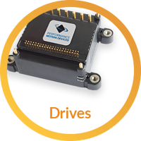
ION/CME N-Series Drives
ION®/CME N-Series Drives are high performance intelligent drives in an ultra-compact PCB-mountable package. In addition to advanced servo and stepper motor control, N-Series IONs provide s-curve point to point profiling, field oriented control, downloadable user code, general purpose digital and analog I/O, and much more. These all-in-one devices make building your next machine controller a snap.
Learn more >>
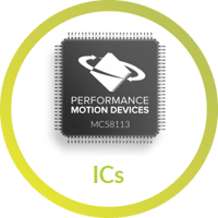
MC58113 Series ICs
The MC58113 series of ICs are part of PMD's popular Magellan Motion Control IC Family and provide advanced position control for stepper, Brushless DC, and DC Brush motors alike. Standard features include FOC (Field Oriented Control), trapezoidal & s-curve profiling, direct encoder and pulse & direction input, and much more. The MC58113 family of ICs are an ideal solution for your next machine design project.
Learn more >>

ION 500 & 3000 Drives
ION 500 and 3000 Drives are high performance intelligent drives in a compact cable-connected package. In addition to advanced servo motor control, IONs provide s-curve point to point moves, i2T power management, downloadable user code, and a range of safety functions including over current, over voltage, and over temperature detect. IONs are easy to use plug and play devices that will get your application up and running in a snap.
Learn more >>

Prodigy/CME Machine Controller
Prodigy®/CME Machine Controller boards provide high-performance motion control for medical, scientific, automation, industrial, and robotic applications. Available in 1, 2, 3, and 4-axis configurations, these boards support DC Brush, Brushless DC, and stepper motors and allow user-written C-language code to be downloaded and run directly on the board. The Prodigy/CME Machine-Controller has on-board Atlas amplifiers that eliminate the need for external amplifiers.
Learn more >>
You may also be interested in:
- PMD Positioning Motion Control ICs Applications Summary (Article)
- OLogic Case Study - Robotics Design Firm (Case Study)
- ION/CME N-Series Drive Applications Summary (Article)
- Build vs. Buy of a Three Axis Motion Controller (Article)